12
W450321A 09/12
3.1 Computer Unit Overview
The Computer Unit is the center of the System. It reads the sensors, controls computations and
disconnect functions, and communicates with the display console/internal bar graph. The two hydraulic
pressure sensors required to sense pressure within the boom hoist cylinder contained within the unit.
These sensors, as well as the computer are factory pre-calibrated as a unit and may not be separately
replaced in the field.
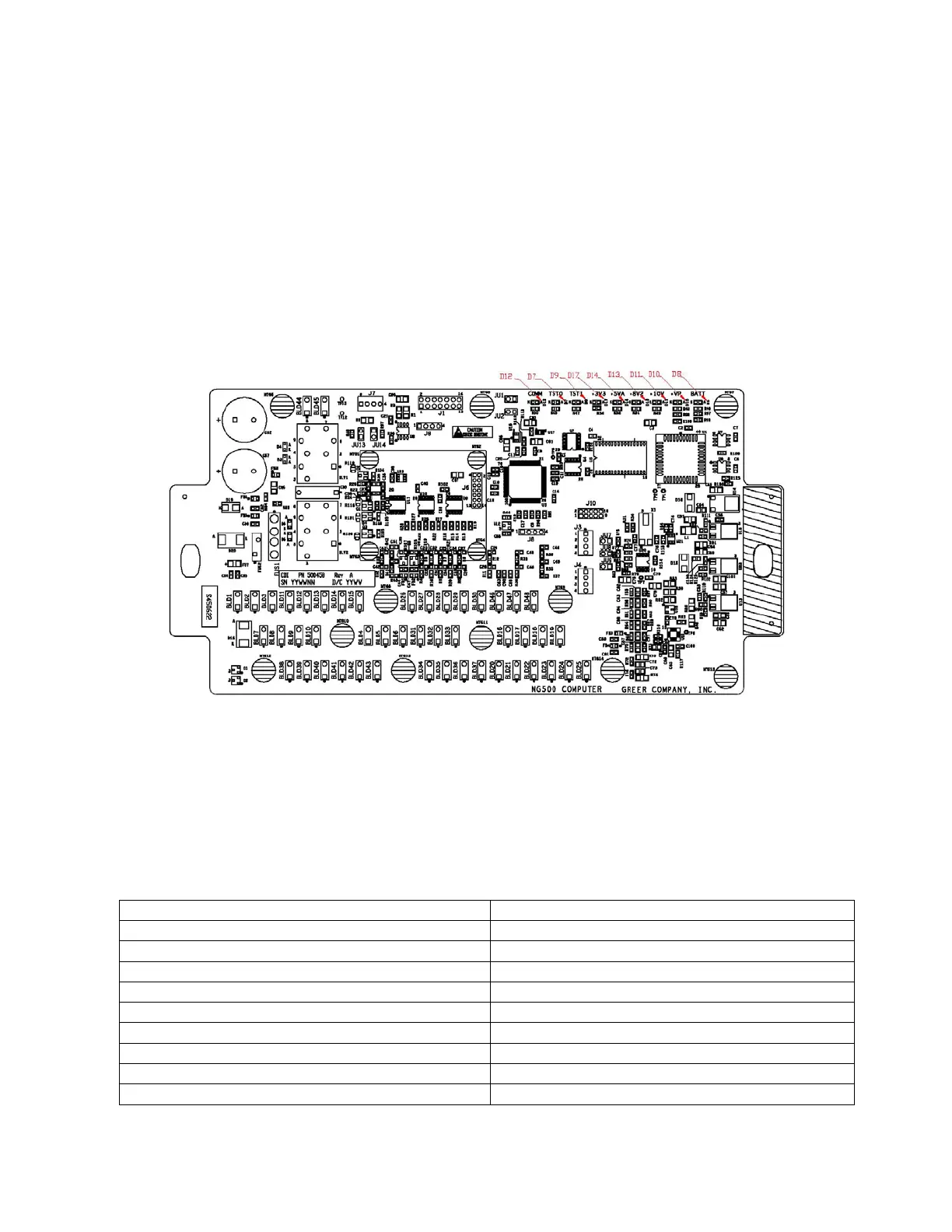
3.2 Computer Unit Layout
NOTE: Due to differences in computer unit configurations, the locations of board components may vary.
Blade Style Computer
3.3 Internal Status Indicators
The computer unit contains a row of LED indicators for checking computer operation. During normal
operation, all LEDs will be illuminated with the COMM indicator blinking. If not, please contact Technical
Support for assistance. Use the following chart and preceding images for LED location.
Communication Indicator TST0
Communication Indicator TST1
COMM (Communication Indicator)