5
DM-R2170-0002A
www.omnexcontrols.com
call toll free: 1-800-663-8806
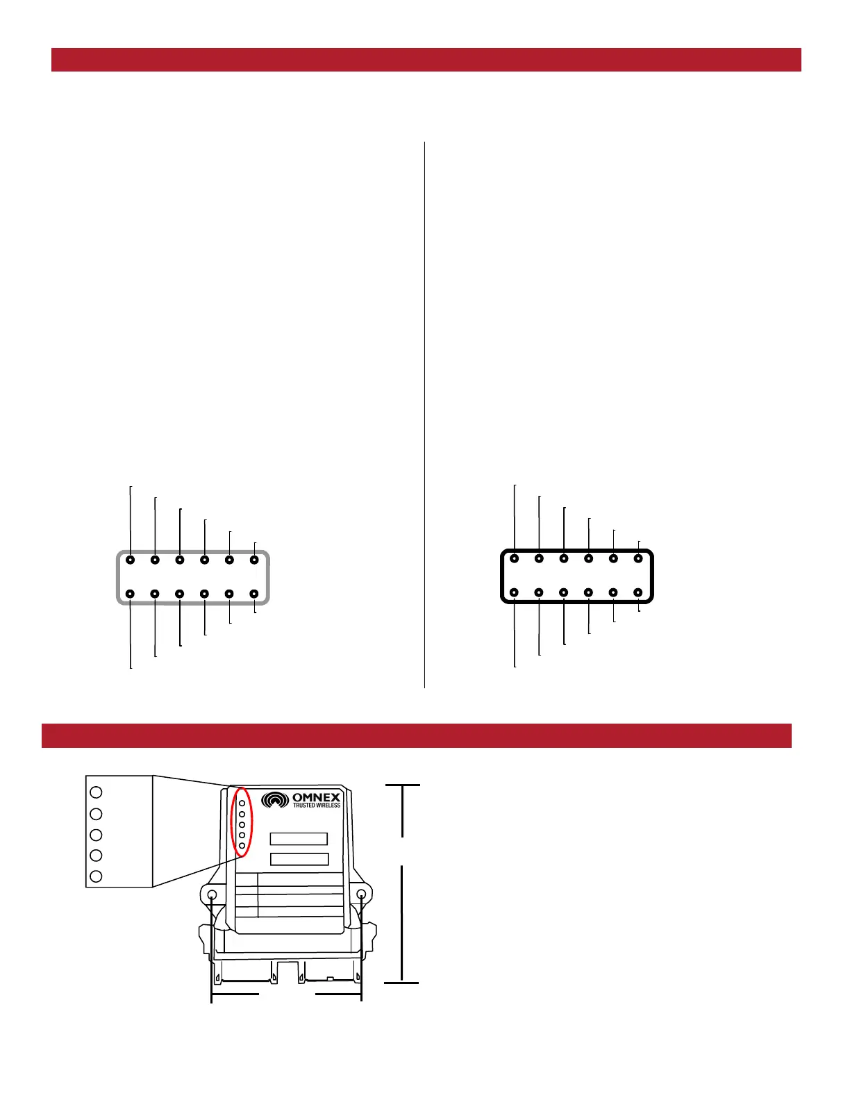
The (Status) light is GREEN when in normal operat-
ing mode.
The (Link) light flashes GREEN to indicate a signal is
being received from an OMNEX transmitter.
The (E-Stop) light is RED when the Emergency-Stop
relay is open and GREEN when the relay is closed
(a valid radio link is received by the R2170).
The (CAN 1) and (CAN 2) lights indicate when the
respective CAN ports are active.
There are two connectors on the R2170. Connector A is Grey, while Connector B is Black. Normally, OMNEX will pro-
vide you with the appropriate pre-terminated cables for connection to the R2170. For reference, the pin functions for
both connectors are provided below:
R2170 Pin Assignments
Connector A (Grey)
Pin Function
1 n/c
2 n/c
3 Main Ground Connection
4 Power in to E-Stop Relay (internally fused to 7.5A)
5 Output of E-Stop Relay
6 Positive Battery supply for R2170 Electronics
7 Ground
8 CAN 1 High
9 CAN 1 Low
10 Ground
11 RS485 A (for Wired Remotes)
12 RS485 B (for Wired Remotes)
RS485 A
n/c
6 5
4
3
2
1
7 8
9 10
11
12
Ground
CAN 1 Low
CAN 1 High
Ground
RS485 B
R2170 power
E-Stop output
E-Stop Power
Main Ground
n/c
R2170 Dimensions and Status Indicators
Connector B (Black)
Pin Function
1 Ground
2 RS232 TX (for serial configuration menus)
3 RS232 RX (for serial configuration menus)
4 Ground
5 CAN 2 High
6 CAN 2 Low
7 n/c
8 n/c
9 n/c
10 Factory Use Only
11 Factory Use Only
12 Factory Use Only
CAN 2 High
Factory Use Only
7 8
9
10
1
1
12
1 2
3 4
5
6
RS232 RX
RS232 TX
Ground
CAN 2 Low
n/c
n/c
n/c
Factory Use Only
Factory Use Only
Ground
4.00”
5.13”
A B
STATUS
LINK
ESTOP
CAN 1
CAN 2
 Loading...