9
DM-R2170-0002A
www.omnexcontrols.com
call toll free: 1-800-663-8806
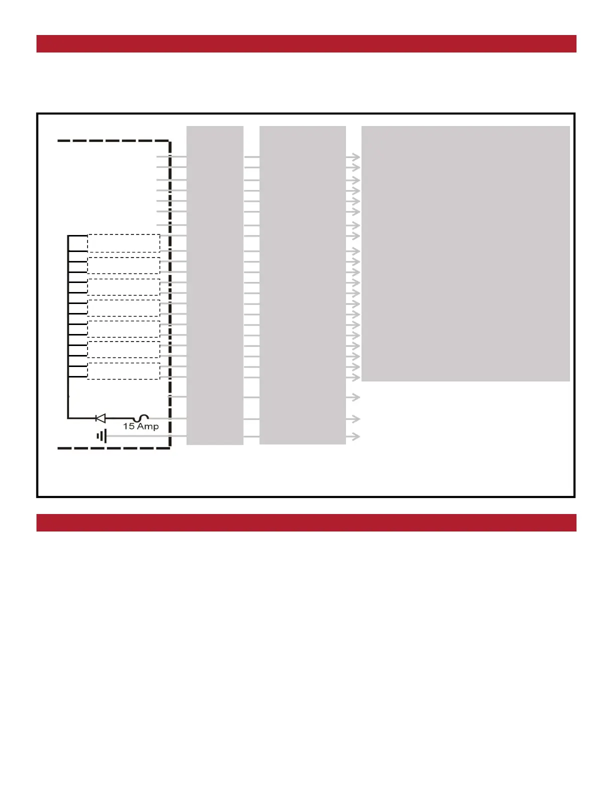
Use the Wiring Diagram and the Connector Diagram below to connect the Expansion module pins directly to the ap-
propriate contacts of the machine electronics. D180 Output Cables are provided with every system to simplify the wir-
ing process. The Wire Color column below only applies to the OMNEX Output Cable configuration. Tips on mounting,
power connections and filtering are also provided under Installation Considerations.
Installing the D180 Expansion Module for T2300-000205
Special Functions
Wiring Diagram
Power Input
(+9V to 30VDC)
Ground
Notes
________________
________________
________________
________________
________________
________________
________________
________________
________________
________________
________________
________________
________________
________________
________________
________________
________________
________________
________________
________________
________________
Functions
Factory Configurable Only
Factory Configurable Only
Unused Output
Unused Output
Unused Output
Unused Output
Unused Output
Unused Output
Unused Output
AUX WINCH UP (Proportional PWM)
AUX WINCH DOWN (Proportional PWM)
WINCH UP (Proportional PWM)
WINCH DOWN (Proportional PWM)
BOOM UP (Proportional PWM)
BOOM DOWN (Proportional PWM)
SPARE DOWN (Proportional PWM)
SPARE UP (Proportional PWM)
BOOM IN (Proportional PWM)
BOOM OUT (Proportional PWM)
BOOM SWING CCW (Proportional PWM)
BOOM SWING CW (Proportional PWM)
Wire Colors
Black/Red
White/Black
Blue/White
Blue/Black
Black/White
Green/Black
Red/White
Orange
White
Green/Black/White
Green
Red/Black/White
White/Red/Black
Orange/Red
Orange/Black
Blue/Red
White/Red
Red/Green
Orange/Green
Black/White/Red
Red
Black
Module 1
Module 2
Module 3
Module 4
Module 5
Module 6
Module 7
Outputs: 14 solid state, high-side driver Current Control outputs 5A max. each, total combined current 15A
D180 Module
Internal Wiring
Pin-Output
B7
B8
B12 - 19
B11 - 18
B10 - 17
A1 - 16
A2 - 15
A4 - 14
B9 - 13
B6 - 12
B5 - 11
B4 - 10
B3 - 9
B2 - 8
B1 - 7
A12 - 6
A10 - 5
A11 - 4
A9 - 3
A8 - 2
A7 - 1
A5
A6
A3
Paddle controlled outputs are set to 50% of the full stroke while the CONTROL RANGE [LOW] switch is latched.
The WINCH [UP, DOWN] functions are enabled while the WINCH [DISABLE] switch is not latched.
All remote functions except TRUCK [START/KILL] must be enabled by pressing the HORN switch. These functions
must be re-enabled after 15 seconds of inactivity.
 Loading...