Digger Safety/Operation EEC-0109 V1.2
Digger Safety and
Operation
The digger drive is powered by a two-speed, piston hydraulic motor. This motor
has a bi-directional “kickdown” system.
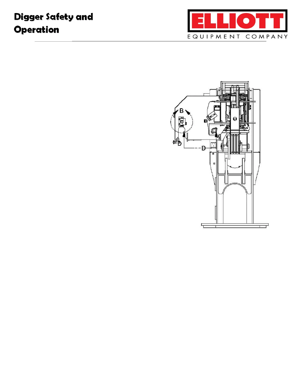
There is an over wind valve (see detail
B in the corresponding system schematic)
mounted on the digger stow bracket. This valve
is also plumbed in parallel with the digger
motor so when stowing the digger, if this valve
is depressed by the auger flighting shaft, the
flow will bypass the digger motor.
There may still be some back pressure
present, and it may not completely stop the
digger drive motor. This back pressure level
depends on several factors such as oil
viscosity, temperature, return filter condition,
etc. do not continue rotating the auger if
contact with the over wind valve does not
stop rotation. Damage may occur to the
wind-up rope or stow bracket, which could
cause the auger to drop.
Auger Latch Circuit
The auger latch consists of a small hydraulic cylinder located inside the stow
bracket. The hoses for this cylinder are run through the hose carrier and connect to an
independent valve section that opens or closes the stow latch. This circuit operates at
crane system pressure.
Auger Latch Proximity Switch
When the digger is deployed, the boom extension must be limited due to
structural issues. This is achieved by limiting the hose carrier beam with a mechanical
stop, and limiting the extend pressure to approximately 600 PSI.
 Loading...