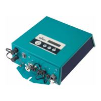
BA-en-3041-2008_PC 29
5 Actual value I
wire color: gray
0…20 mA (output):
0 mA corresponding to 0 mA output current
20 mA corresponding to 7.5 mA output current
Max. load: 500
6 Analog setpoint
wire color: pink
for setting the voltage or current setpoint (input);
see the table “Setting options” below.
7 Actual value U
wire color: blue
0…20 mA (output):
0 mA corresponding to 0 kV, 20 mA corresonding to U
max
;
see overwiew of the variants, table page 9
8 GND for max. load: 500 24 V DC output
wire color: red
fault signals, analog setpoint and actual values
Setting options:
* Values U
max
resp. I
max
see table page 11
The fault signal output can additionally be used when the limiter signal is
activated; reaching a limit the display shows:
• fault signal output 0 V: limiter active
• fault signal output 24 V DC: no limiter active
OFF No change of the setpoint
Current 0 - 20 mA 20 mA correspond to the maximum output value *
Voltage 0 - 10 V 10 V correspond to the maximum output value *
 Loading...