EMC
®
VNX
™
Procedure Generator
EMC CONFIDENTIAL version: 4.5
20 of 51
You hear an audible click when the tab is pressed and the latch is released.
4. [ ] Lower the latch to release the power/cooling module from the CPU module.
Note: The orange tabs on the power/cooling module are labeled with a 1.
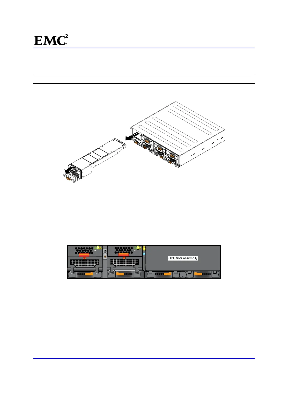
5. [ ] Pull the power/cooling module out of the chassis (Figure 8) and place it on an antistatic surface.
CL3972
Figure 8 Removing a Power/Cooling module
Remove the CPU Filler Assembly
If present, remove the CPU filler assembly. Otherwise, skip to the next task. To remove the CPU filler
assembly:
6. [ ] Locate and press the orange latches away from each other to fully release the CPU filler assembly
(Figure 9).
AC
AC
ACAC
Figure 9 CPU Filler assembly Location (front)
7. [ ] Using these latches, remove the CPU filler assembly.
8. [ ] Place the CPU filler assembly on a static-free work bench, mat, or static-free bags for protection.

 Loading...


