EMC
®
VNX
™
Procedure Generator
EMC CONFIDENTIAL version: 4.5
21 of 51
9. [ ] Install the CPU modules from the Blade in the replacement chassis in the corresponding locations
from which they were removed.
10. [ ] Install power/cooling modules into the replacement chassis in the corresponding locations from
which they were removed.
Removing a CPU module
Both power supply cooling modules must be removed before the CPU module can be removed from the
chassis.
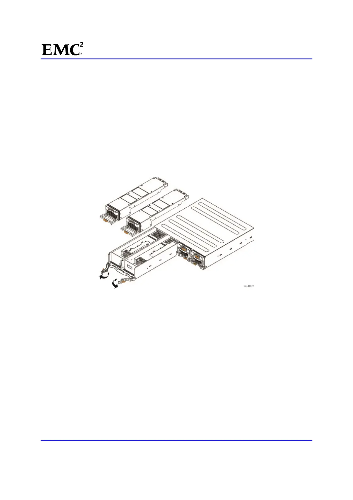
11. [ ] Press the orange tabs (labeled with a 2) toward each other to unlock the latches (Figure 10).
12. [ ] Push the latches away from each other to fully release the CPU module (Figure 10).
13. [ ] Pull the CPU module from the chassis (Figure 10).
Figure 10 Removing a CPU module
Installing a CPU module
14. [ ] Align the CPU module with the chassis and slide it into position (Figure 11).
15. [ ] Push the latches toward each other to fully seat and lock the CPU module in place (Figure 11)

 Loading...


