EMC
®
VNX
™
Procedure Generator
EMC CONFIDENTIAL version: 4.5
39 of 51
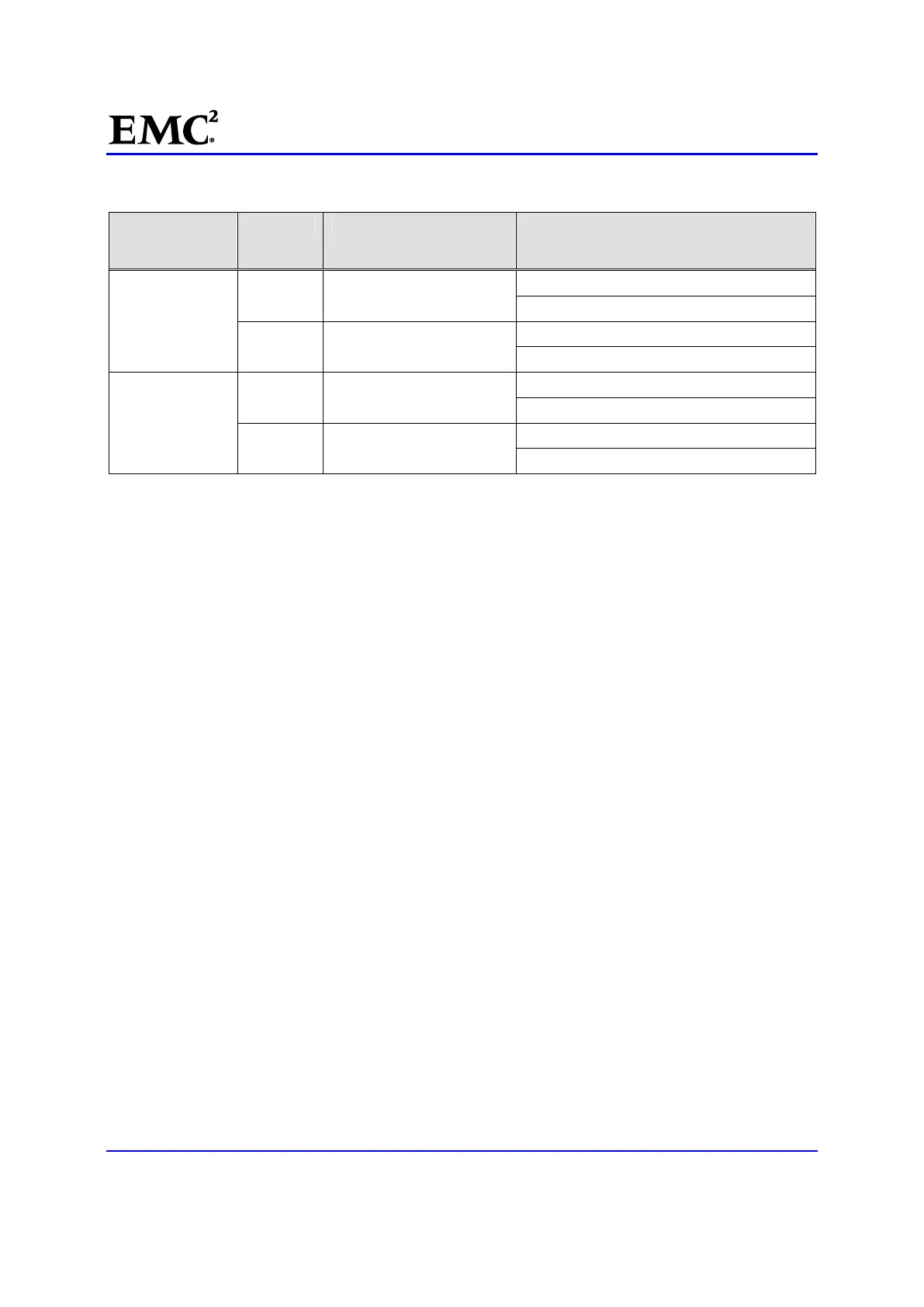
Table 6 Construct the new Blade port WWNs
Blade number Blade port Blade port WWN (HBA UID) SP and port SP ports marked with an * only
apply to a fabric-connected gateway. Do not
use for a direct-connected gateway.
Blade ____
(even-numbered
Blade)
0 (HBA 0) SP A - port ___
SP B* - port ___
1 (HBA 1) SP A* - port ___
SP B - port ___
Blade ___
(odd-numbered
Blade)
0 (HBA 0) SP A - port ___
SP B* - port ___
1 (HBA 1) SP A* - port ___
SP B - port ___
1
SP ports marked with an * only apply to fabric-connected gateway. Do not sue for a direct-connected
gateway.
Zone the FC switch(s)
For fabric-connected gateway platforms, configure the switch zoning at this time. Otherwise, skip to
Recreate the initiator records.
If the Blade enclosure contains Blades with fibre channel optical ports connected to a Fibre Channel (FC)
switch, the FC switch will need to be rezoned with the new WWNs of these FC optical ports. Follow the
instructions in the "Zoning FC Switches and Manually Configuring System LUNs" appendix in the
EMC
(R)
VNX
(TM)
VG2/VG8 Gateway Configuration Phase 1 and 2 Setup Guide (P/N 300-012-157) found on
www.Powerlink.EMC.com.
Recreate the initiator records
To recreate the initiator records:
13. [ ] Display the Blade port to SP port FCP records for each Blade in the replacement BE. Record the
SP port value in Table 6.
# /nasmcd/sbin/t2tty -c <slot_number> "fcp show" | egrep "HBA 0 HBA 1"
where <slot_number> is the slot number of each Blade in the replacement BE.
Two examples are presented below. Example 1 shows the commands and output for Blade enclosure 0
in a Unified, File, or direct-connect gateway. Whereas, Example 2 is a model for a gateway in a
fabric-connect configuration. Follow the example that reflects the system’s configuration.
Example 1:
Example 1 shows the commands and output for Blade enclosure 0 in a Unified, File, or direct-connect
gateway. With:
Blade 2 - port 0 (HBA 0) connected to SP A - port 0
Blade 2 - port 1 (HBA 1) connected to SP B - port 1
Blade 3 - port 0 (HBA 0) connected to SP A - port 0

 Loading...


