EMC
®
VNX
™
Procedure Generator
EMC CONFIDENTIAL version: 4.5
23 of 51
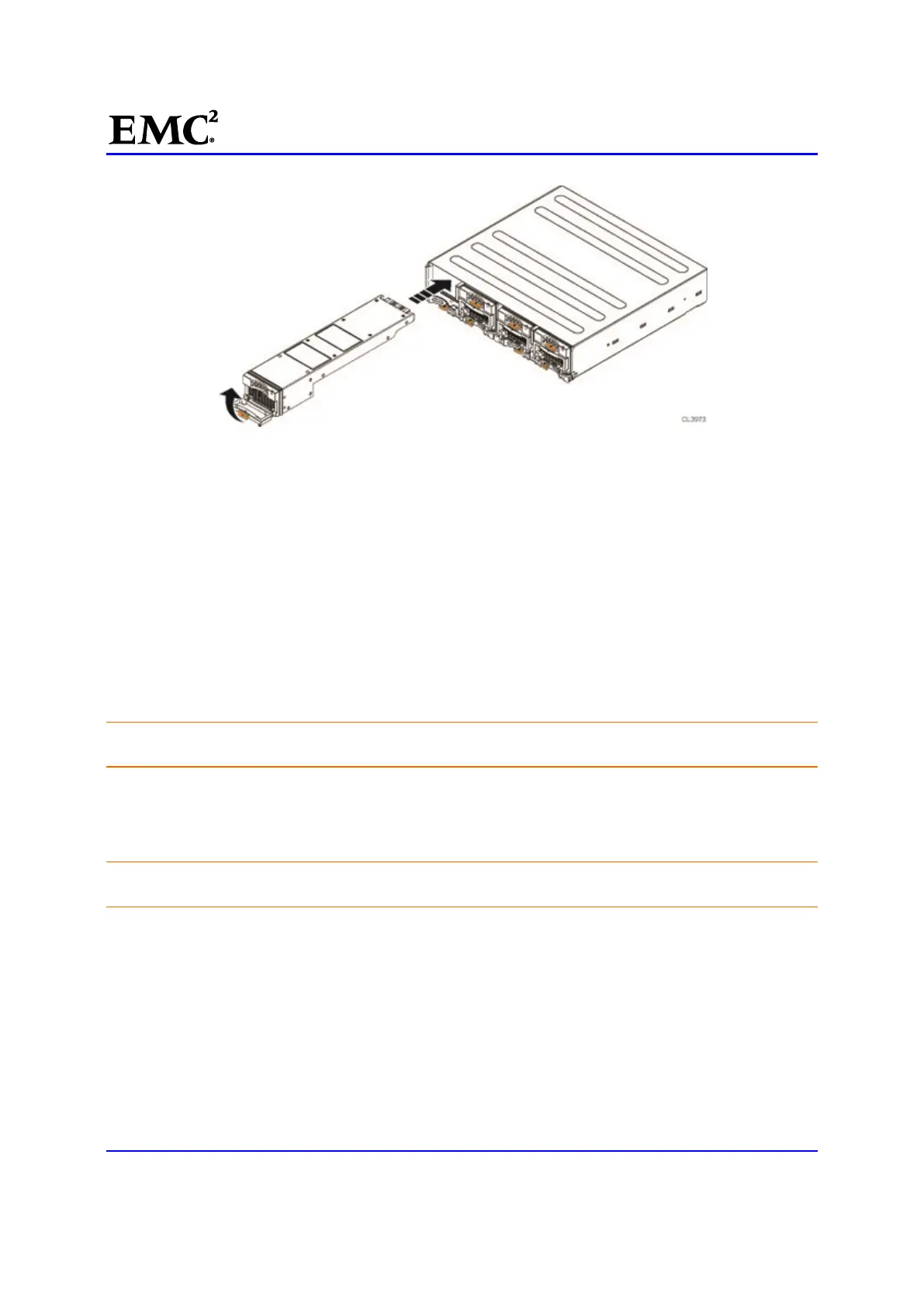
Figure 12 Installing a Power/Cooling module
21. [ ] Reconnect the power cord to the power/cooling module.
Transfer Management Modules and I/O Modules
You must transfer the management modules and I/O modules from the faulted chassis to the same
locations in the replacement chassis.
For each Blade, starting with the components on the A side (from the rear of the system, this is the right
side), complete the following steps, as described in the sections that follow, to transfer the management
modules and I/O modules:
Removing a Management Module
To remove a management module from a Blade enclosure in the system:
CAUTION: Observe ESD procedures; handle the Blade components with care. You can remove a
management module while the system is powered up.
22. [ ] Use masking tape or similar material to label each cable to correctly reconnect them later.
23. [ ] Disconnect the Ethernet cables from the module.
Carefully press the connector latches to release them before you remove the cables.
CAUTION: Do not bend, pull, or stress other cables. Dress and secure the cables to one side so
that you can remove a management module without damaging the cables.
24. [ ] On the management module, pull the trigger mechanism on the module handle to release it from
the Blade enclosure Figure 13.

 Loading...


