Cable your system
17
Cable your system
Cables for your system have cable labels pre-attached.
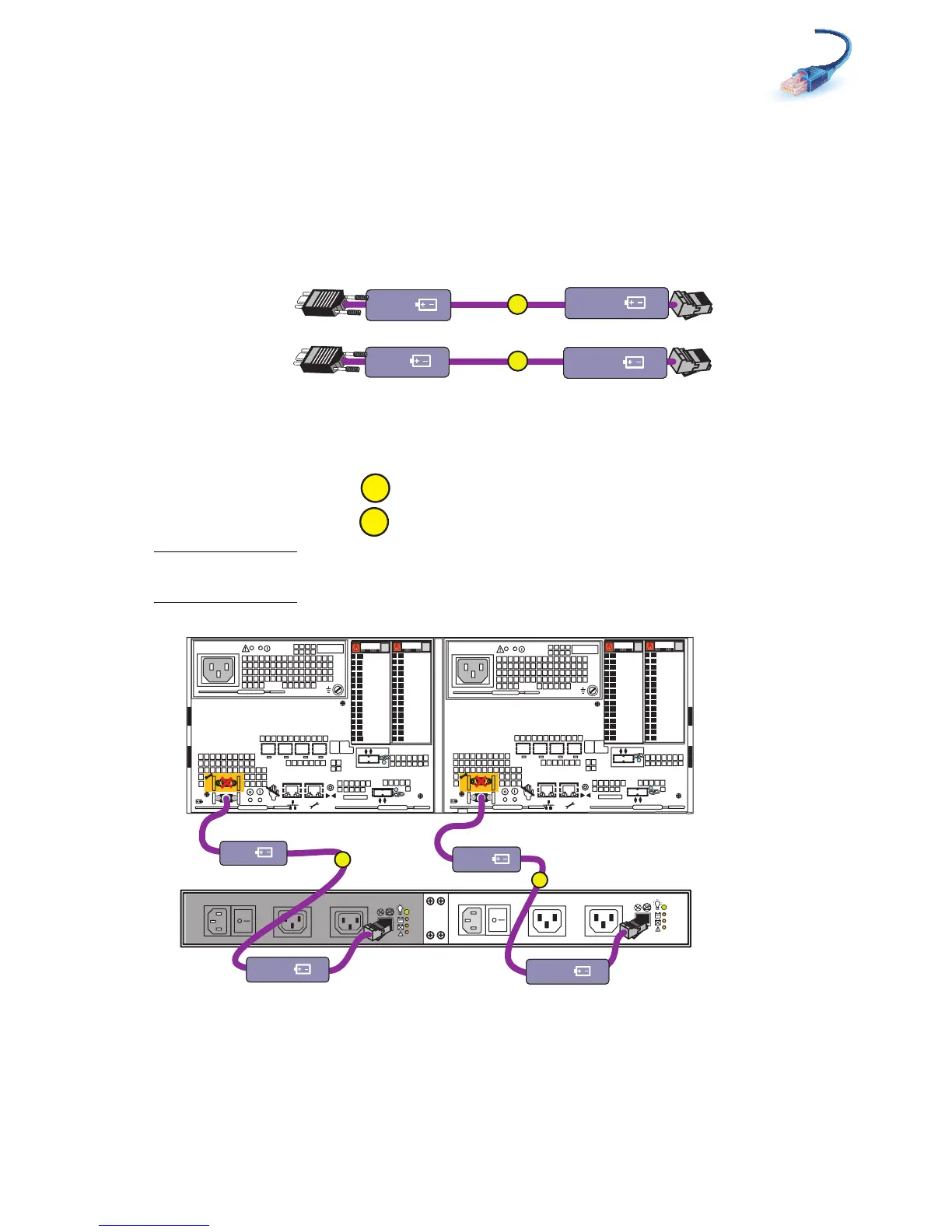
Cabling the standby power supply to SP serial port
1. Locate the cables shown in Figure 7. These cables have RJ45 connections on one end and a
9-pin mini-connector on the other.
Figure 7 Cables connecting SPS to SP
2. Connect SPS A to SP A.
3. Connect SPS B to SP B.
Note: SPS B is optional. If you do not have SPS B in the enclosure, your system will not have cable
B to attach.
Figure 8 Cabling to management ports
A
B
SPS A
SPS B
SP B
SP A
VNV-000226
A
X4
2
3
4
5
6Gb
SAS
8Gb
bre
1
0 X4
6Gb SAS
X4
2
3
4
5
6Gb
SAS
8Gb
bre
1
0 X4
6Gb SAS
B
A
Disk processor enclosure
SPS B
Power
Power
Switch
Power
Power
Switch
Standby power supply
SPS A
SPS B optional
VNX-000134
B
SP B
SP A
SPS B
SPS A
A
 Loading...