J. Acquisition Module
K. Base electronics enclosure
L. Cable glands
M. U.L. warning tag - Base enclosure
N. M20 plug
O. Gasket
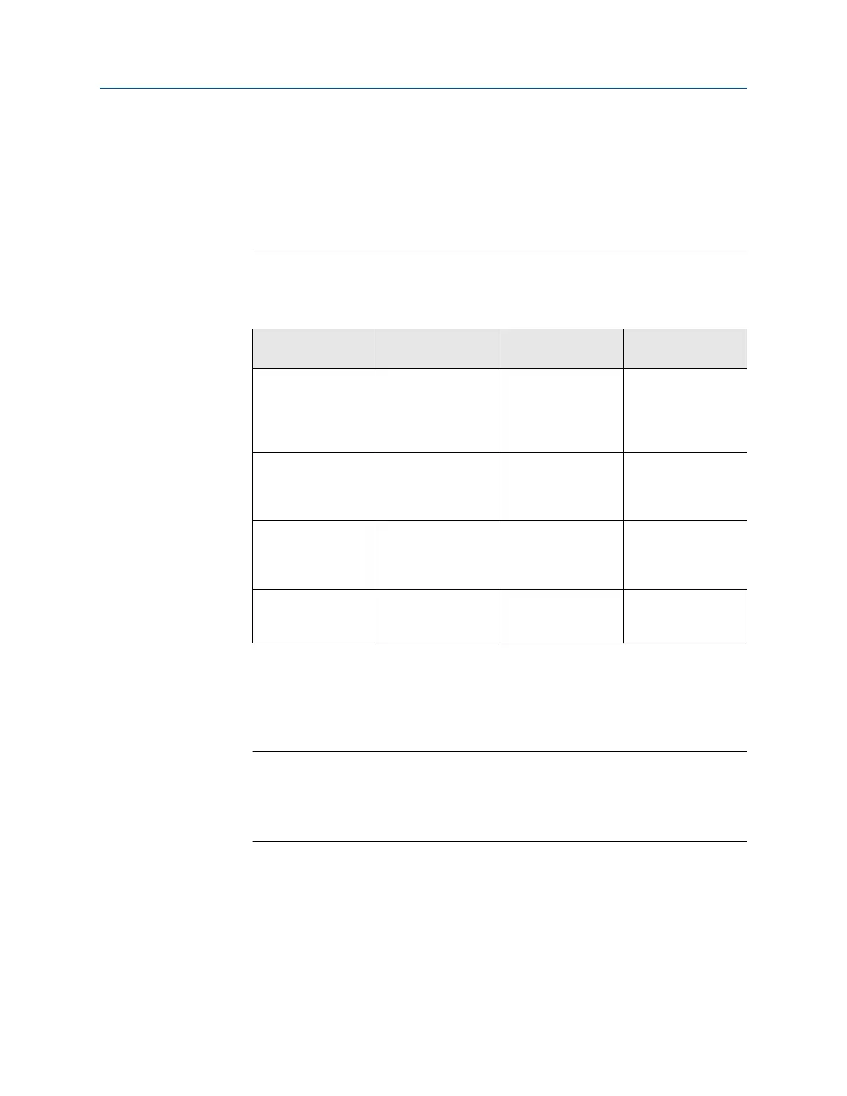
The following table shows the default communications and output settings for the
3410 electronics and configuration.
Table 5-1: 3410 Series default communications and output settings
Communication/
Output Type
Default Setting Default Setting Note
Serial Port A Modbus ID = 32 Baud Rate = 19200 Port B and Port C are
available if Optional
RS-232 and RS- 485
I/O Modules are
installed
Frequency/Digital
Output 1
Configured to output
Frequency 1A
Drive Mode=Open
Collector
Frequency Output 1A
is configured for
Uncorrected forward
flow
Frequency/Digital
Output 2
Configured to output
Frequency 2A
Drive Mode=Open
collector
Frequency Output 2A
is configured for
Uncorrected forward
flow
Frequency/Digital
Output 3
Configured to output
Digital Output 1A
Drive Mode=Open
Collector
Digital Output 1A is
configured for
Validity status
If the settings above are not consistent with those used in your meter, then these
parameters can be changed using Daniel MeterLink
™
software to reconfigure the
communication ports and output ports later in this procedure. Appendix C of this
document contains additional details with respect to the wiring related to the
communications and discrete output signals.
Notice
Daniel MeterLink
™
cannot communicate with 3410 meters over a half-duplex serial
connection. As a result, for Daniel MeterLink to communicate via a serial
connection, that port on the 3410 electronics must be set for RS-232-Full Duplex, or
RS-485-Full Duplex (requires 4 conductor cables).
25. Check the CPU Module switches on the to ensure they are set properly.
Upgrade kit instructions Installing the 3410 Series Electronics
P/N 3-9000-784 July 2019
3410 Series Electronics Upgrade kit instructions 39

 Loading...


