5 Installing the 3410 Series Electronics
5.1 Procedure to install the 3410 Series Electronics
Procedure
1. Remove the 3410 Upgrade components from the packaging.
a) Use the 6 mm Allen wrench to remove the two screws from the base
enclosure cover.
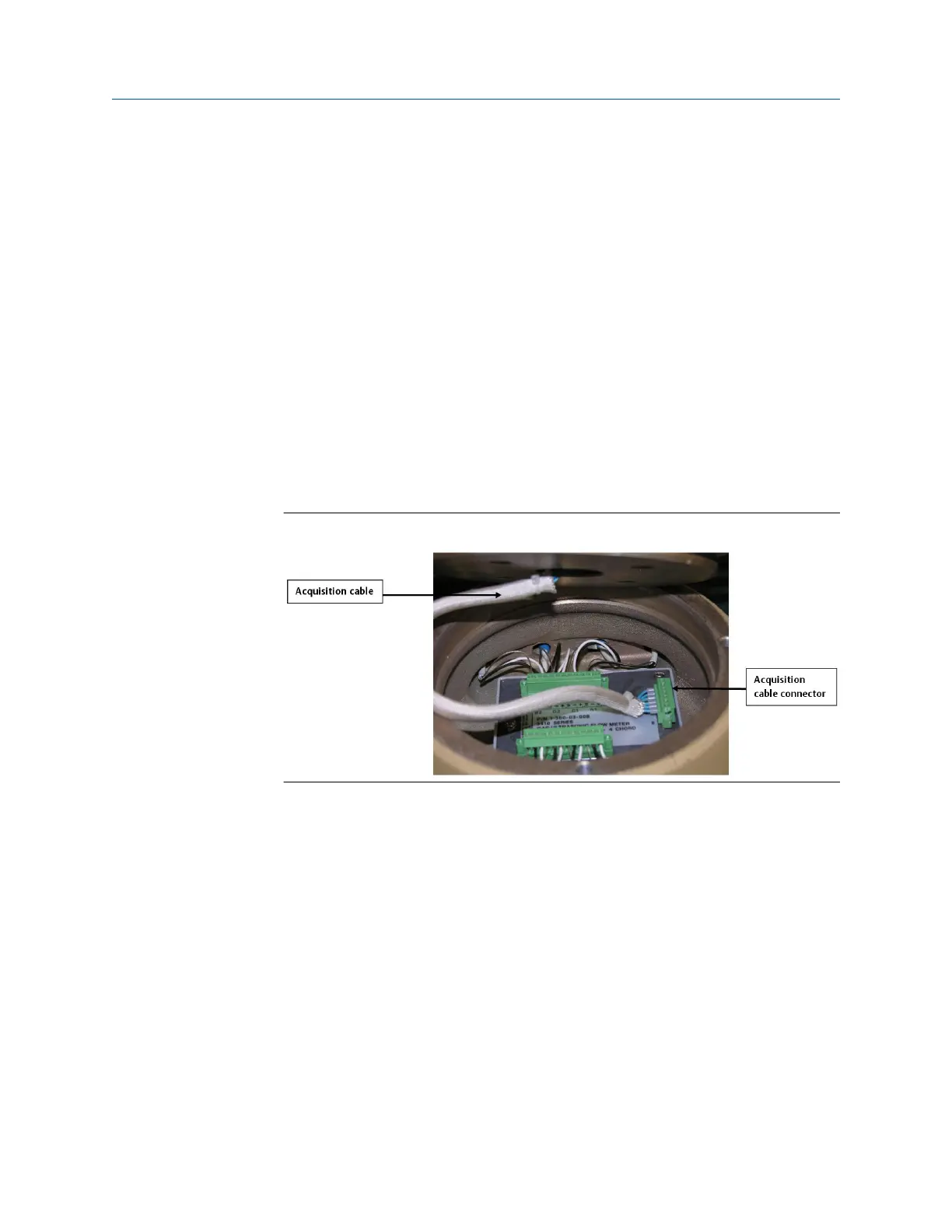
2. Lift the upper electronics housing from the base enclosure. The acquisition cable
connector from the upper electronics is attached to the acquisition module with
two screws. The cable is also secured by a cable clamp to a mounting bolt.
a) Remove the screw securing the cable clamp and then loosen the two screws
on the acquisition cable connector and disconnect the acquisition cable
connector from the acquisition module.
Figure 5-1: Remove acquisition cable and module
3. Unscrew the remaining two mounting screws from the acquisition module in the
base enclosure and remove the acquisition board.
4. Place an insulating gasket on the meter body where the electronics will be mounted
(see gasket in Figure 3-4).
5. Place the base enclosure on top of the meter body on top of the insulating gasket.
Note that the transducer port openings on the base enclosure are labeled with
transducer locations (i.e., A1, A2, B1, B2, C1, C2, D1, D2).
a) Orient the base so that the A1 transducer port is closest to the A1 transducer
location on the meter body. The meter body has the transducer location
labels embossed in the body next to each transducer boss. The ports on the
base enclosure must be oriented outward (towards the sides of the meter
body, perpendicular to meter axis).
Upgrade kit instructions Installing the 3410 Series Electronics
P/N 3-9000-784 July 2019
3410 Series Electronics Upgrade kit instructions 29

 Loading...


