B Communication/Output settings
B.1 Summary table of communications/output
settings
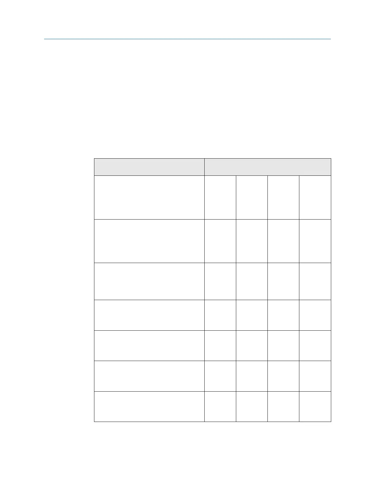
Based on switch position on the 3400 CPU board and Option board if installed, indicate the
appropriate configuration for each communication/output parameters on the 3400
electronics. Use these parameters to configure the 3410 Series electronics.
Table B-1: Communications/output settings summary table
Output Type (Check electronics switch settings and circle
appropriate box for each output)
Serial Port A Not Used
(if J6 not
used)
RS-232 (if
S3 is set to
RS232)
RS-485
Half Duplex
(if S3 is set
to RS-485
and S5-1 is
set to Half
RS-485 Full
Duplex (if
S3 is set to
RS-485 and
S5-1 is set
to Full
Serial Port B Not Used
(if J7 not
used)
RS-232 (if
S4 is set to
RS232)
RS-485
Half Duplex
(if S4 is set
to RS482
and S5-2 is
set to Half)
RS-485 Full
Duplex (if
S4 is set to
RS-485 and
S5-2 is set
to Full)
Serial Port C Not Used
(if J16 not
used)
RS-232 (if
S10 is set
to RS232)
RS-485
Half Duplex
(if S10 is
set to
RS-485)
Digital Output 1A Not Used
(if J4-2 not
used)
TTL (if S8-1
is set to
TTL)
Open
Collector (if
S8-1 is set
to OC)
Digital Output 1B Not Used
(if J4-1 not
used)
TTL (if S8-2
is set to
TTL)
Open
Collector (if
S8-2 is set
to OC)
Frequency Output 1A Not Used
(if J4-1 not
used)
TTL (if S8-3
is set to
TTL)
Open
Collector (if
S8-3 is set
to OC)
Digital Output 2A Not Used
(if J5-2 not
used)
TTL (if S9-1
is set to
TTL)
Open
Collector (if
S8-1 is set
to OC)
Upgrade kit instructions Communication/Output settings
P/N 3-9000-784 July 2019
3410 Series Electronics Upgrade kit instructions 71

 Loading...


