10 • iPro I/O Module Installation and Operation Manual 026-1741 Rev 0
2.1.1 10 DIN Panel Supply Power
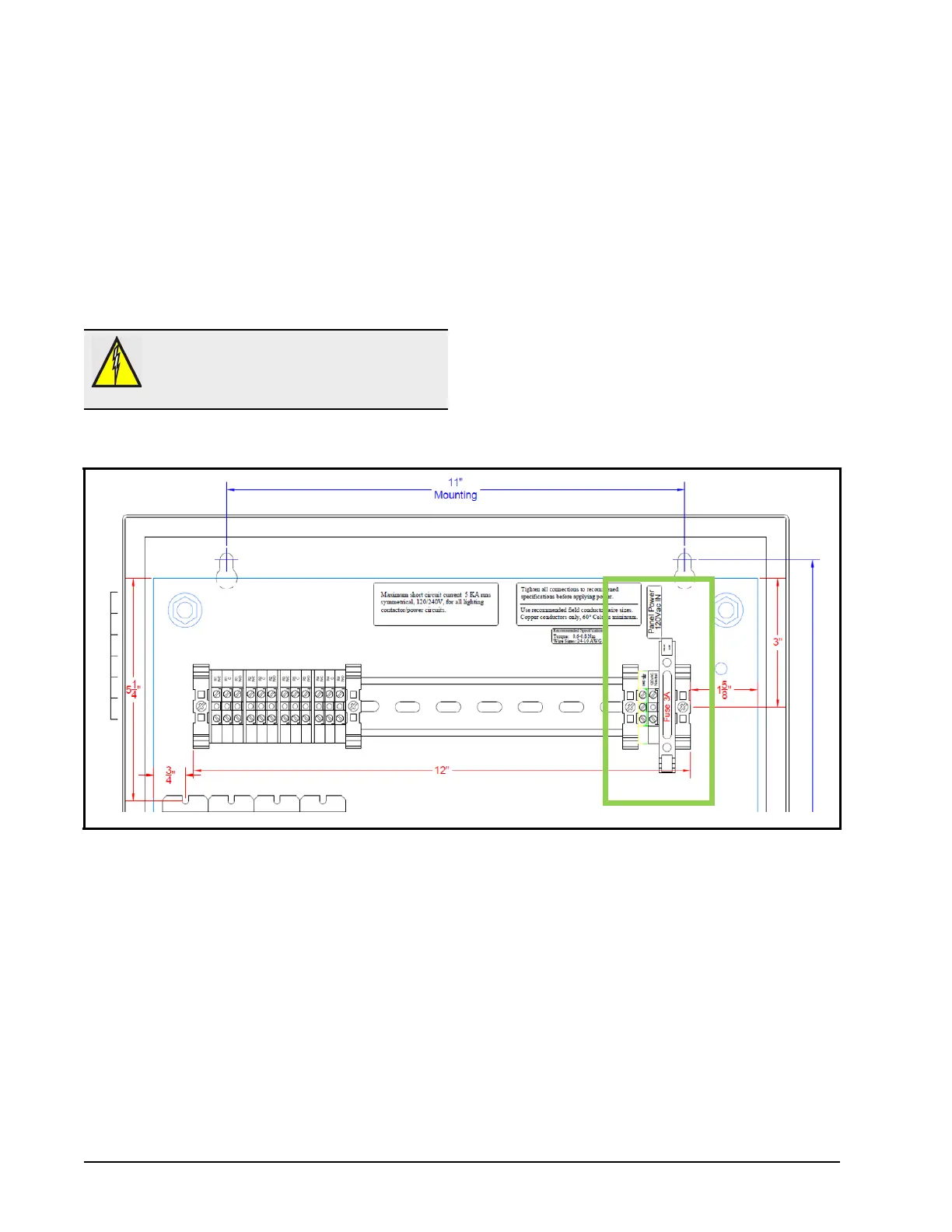
The supply power for the panel should be 120VAC,
60 Hz, single phase. An upstream disconnect and circuit
protection (MCCB, 20A max) supplied by the installer is
required for the control circuit. The supply power
connection is made at the terminal block in the top right
corner of the panel on connections 120V Hot, 120V
Neutral and GND. All guidelines and recommendations on
the panel labels must be followed when wiring the supply
power.
2.1.2 10 DIN Panel Temperature Sensor Wiring
The 851-4445 panel provides analog inputs factory wired to a terminal block on the panel back plate for easy connection
of input sensors. Figure 2-4 shows wiring detail for connecting temperature sensors. Connect one side of the temperature
leads to the Pb1 connection and the other side to the PbC probe Common. If more than 1 temperature sensor is used, the
PbC Common terminal is used for the Common terminal of all sensors. The PbC probe Common should only be used for
resistive type inputs and not voltage/current inputs. If temperature sensors must be extended beyond the factory leads,
Emerson specifies P/N 135-0600 22/2 shielded cable.
WARNING: All power must be shut off prior to
wiring, installation or service. More than one
disconnects may be required to de-energize this
panel.
Figure 2-3 - 10 DIN Panel Supply Power