12 • iPro I/O Module Installation and Operation Manual 026-1741 Rev 0
0 to 1 VDC, 0 to 5 VDC, and 0 to 10 VDC Sensor
Wiring
Other voltage type inputs that require 5V or 12V power
can be wired similar to the 5 volt transducer. Connect the
input signal wire to one of the Pb inputs on the terminal
strip. If the sensor requires 5V power supply, attach the
sensor power supply wire to +5V pin 15 on the terminal
strip; 12V can be sourced from the +12 V pin 16 on the
terminal strip. For all voltage type inputs the GND
terminal is used, not the PbC probe Common.
2.1.4 10 DIN Panel 4-20mA Input
Wiring
The 851-4445 panel provides analog inputs factory wired
to a terminal block on the panel backplate for easy
connection of input sensors. The I/O Module can accept
4 to 20mA type inputs that have their own separate power
supply or that require supply power from I/O Module.
Figure 2-6 shows wiring detail for current inputs with and
without their own power supply.
2.1.5 10 DIN Panel Relay Wiring
and Specifications
The 10 DIN control panel comes factory-wired with four
(4) single pole double throw pilot relays with form C
contacts (Emerson P/N 221-1132). The relay coil (24VAC)
circuit is already factory-wired to the I/O Module Onboard
relays; R1 pilot relay is controlled directly from the I/O
Module relay 1. Installers need only to make connections
to the factory terminal block for the load circuit that needs
to be controlled. The pilot relay specifications can be
found in the Table 2-1 and the panel terminal strips are
shown in Figure 2-7.
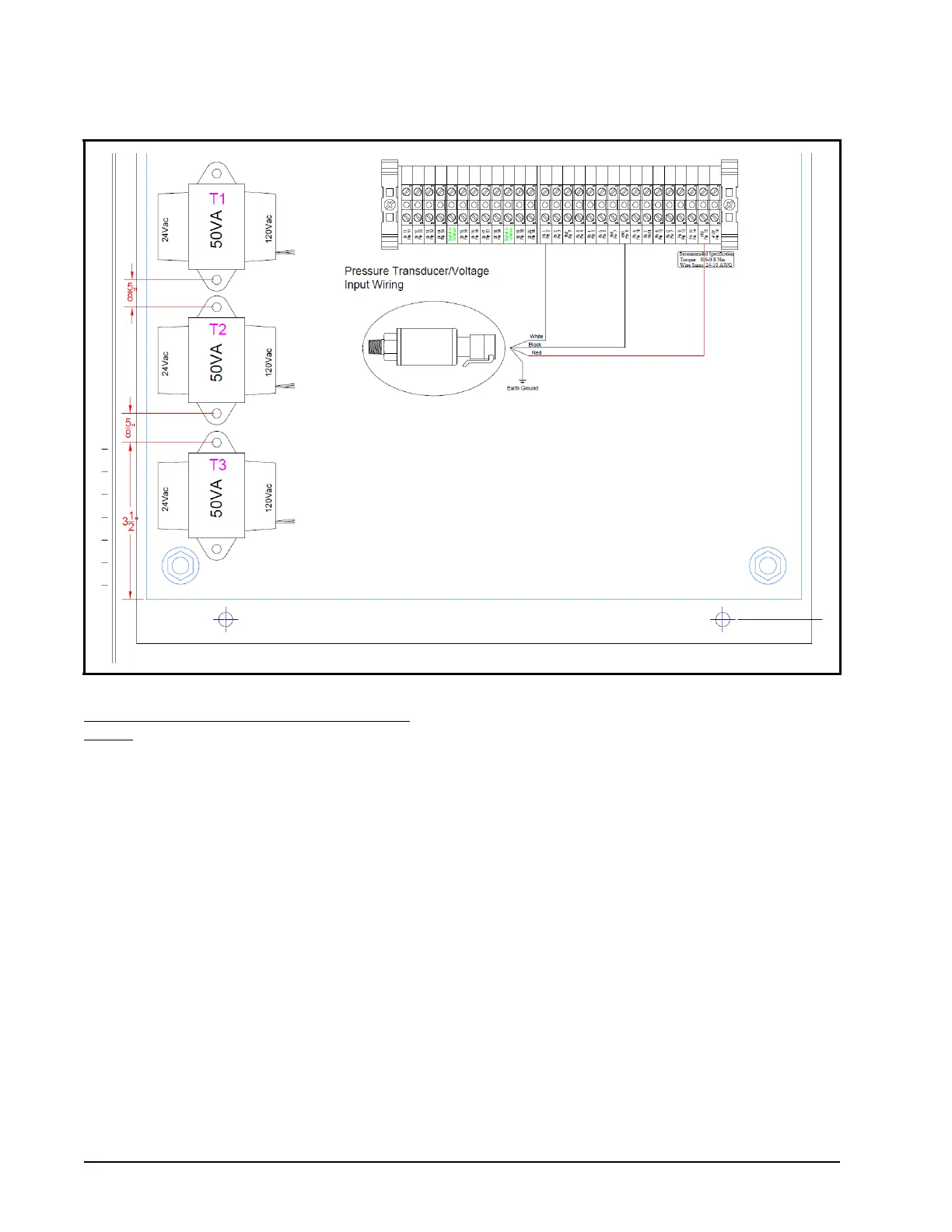
Figure 2-5 - Emerson Pressure Transducer Input Wiring