44 Micro Motion
®
Model 2400S Transmitters with Analog Outputs
Required Transmitter Configuration
6.5 Configuring the mA output
The Model 2400S AN transmitter has one mA output. Table 6-8 lists the parameters that must be set
for the mA output, and shows the names used for each parameter by the display, ProLink II, and the
Communicator.
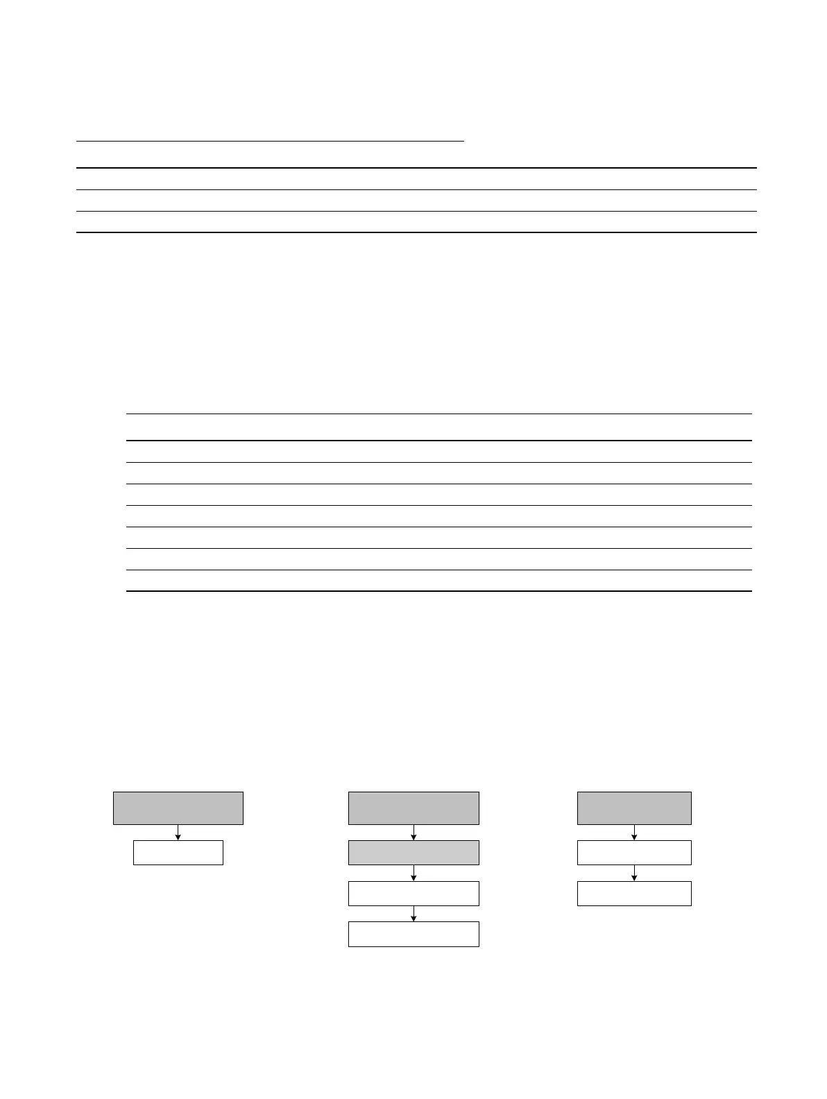
To configure the mA output, see the menu flowcharts in Figure 6-5. For details on mA output
parameters, see Sections 6.5.1 through 6.5.4.
Note: If you use the display to configure the mA output, you can configure only the process variable
and the range. To configure other mA output parameters, use ProLink II or the Communicator.
Figure 6-5 Configuring the mA output
MPA megapascals MPa Megapascals
TORR Torr
@ 0C torr Torr @ 0 °C
ATM atms atms Atmospheres
Table 6-8 mA output configuration parameters
Parameter name
ProLink II Communicator Display
Primary variable PV SRC
Lower range value PV LRV 4 MA
Upper range value PV URV 20 MA
AO cutoff PV AO cutoff Not applicable
AO added damp PV AO added damp Not applicable
AO fault action AO1 fault indicator Not applicable
AO fault level mA1 fault value Not applicable
Table 6-7 Pressure measurement units continued
Pressure unit
Unit descriptionDisplay ProLink II Communicator
IO
CH A
Off-line maint >
Off-line config
Analog output
ProLink >
Configuration
1 Channel setup
4 AO setup
On-Line Menu >
5 Detailed Setup
3 Config outputs
Communicator DisplayProLink II



 To Next Page