50 Micro Motion
®
Model 2400S Transmitters with Analog Outputs
Required Transmitter Configuration
The resulting TV Frequency Factor value must be within the range of the frequency output (0 to
10,000 Hz).
• If the TV Frequency Factor value is less than 1 Hz, reconfigure the receiving device for a
higher pulses/unit setting.
• If the TV Frequency Factor value is greater than 10,000 Hz, reconfigure the receiving device
for a lower pulses/unit setting.
6.6.3 Configuring the maximum pulse width
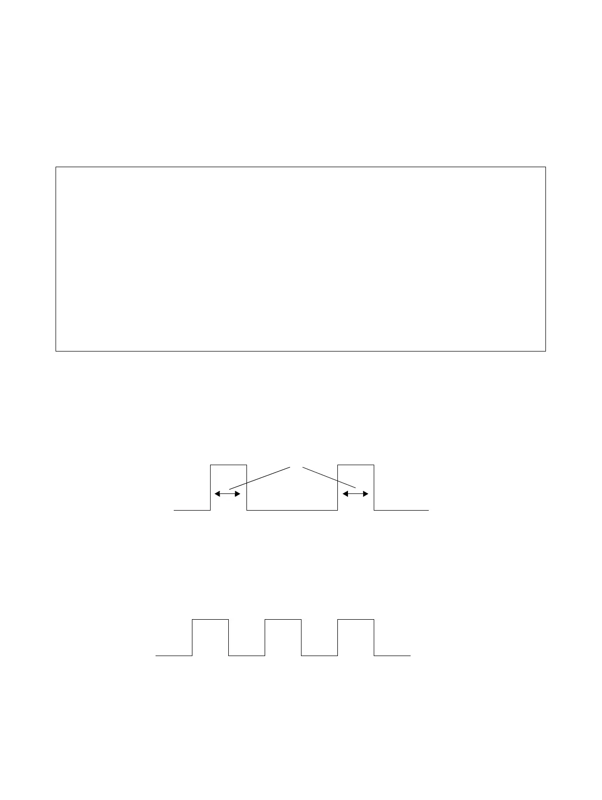
The frequency output maximum pulse width defines the maximum duration of each pulse the
transmitter sends to the frequency receiving device, as shown in Figure 6-7.
Figure 6-7 Pulse width
Maximum Pulse Width can be set to 0, or to values between 0.01 and 655.35 milliseconds, in 0.01
millisecond increments. If Maximum Pulse Width is set to 0 (the default), the output will have a 50%
duty cycle, no matter what the frequency is. A 50% duty cycle is illustrated in Figure 6-8.
Figure 6-8 50% duty cycle
If Maximum Pulse Width is set to a non-zero value, the duty cycle is controlled by the crossover
frequency. The crossover frequency is calculated as follows:
Example
Maximum appropriate flowrate (TV Rate Factor) is 2000 lbs/min.
Receiving device is configured for 10 pulses/pound.
Solution:
Configuration:
• TV Frequency Factor = 333.33
• TV Rate Factor = 2000
FrequencyFactor
Rate
T
------------
N×=
FrequencyFactor
2000
60
-------------
10×=
FrequencyFactor 333.33=



 To Next Page