Configuration and Use Manual 51
Required Transmitter Configuration
Required Configuration Optional ConfigurationUsing the TransmitterFlowmeter Startup
• At frequencies below the crossover frequency, the duty cycle is determined by the pulse width
and the frequency.
• At frequencies above the crossover frequency, the output changes to a 50% duty cycle.
You can change the setting for Maximum Pulse Width so that the transmitter will output a pulse width
appropriate to your receiving device:
• High-frequency counters such as frequency-to-voltage converters, frequency-to-current
converters, and Micro Motion peripherals usually require approximately a 50% duty cycle.
• Electromechanical counters and PLCs that have low-scan cycle rates generally use an input
with a fixed nonzero state duration and a varying zero state duration. Most low-frequency
counters have a specified requirement for Maximum Pulse Width.
Note: For typical applications, the default pulse width is used.
6.6.4 Configuring the frequency output polarity
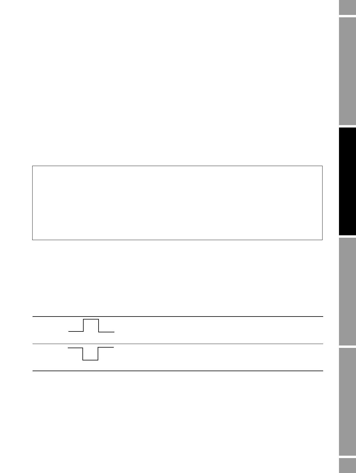
The frequency output polarity controls how the output indicates the active (ON) state. See Table 6-14.
The default value, Active High, is appropriate for most applications. Active Low may be required by
applications that use low-frequency signals.
Example
The frequency output is wired to a PLC with a specified pulse width
requirement of 50 ms. The crossover frequency is 10 Hz.
Solution:
• Set Max Pulse Width to 50 ms.
• For frequencies less than 10 Hz, the frequency output will have a
50 msec ON state, and the OFF state will be adjusted as required.
For frequencies higher than 10 Hz, the frequency output will be a
square wave with a 50% duty cycle.
Table 6-14 Polarity settings and frequency output levels
Polarity Reference voltage (OFF) Pulse voltage (ON)
Active high 0 As determined by power supply,
pull-up resistor, and load (see the
installation manual for your
transmitter)
Active low As determined by power supply,
pull-up resistor, and load (see the
installation manual for your
transmitter)
0
Crossover frequency
1
2 max pulse width×
----------------------------------------------------=



 To Next Page