48 Micro Motion
®
Model 2400S Transmitters with Analog Outputs
Required Transmitter Configuration
6.6 Configuring the frequency output
Note: This section is applicable only if Channel B has been configured as a frequency output. See
Section 6.3.
The frequency output generates two voltage levels:
•0 V
• A site-specific voltage, determined by the power supply, pull-up resistor, and load (see the
installation manual for your transmitter)
If Channel B is configured as a frequency output, you must configure the parameters listed in
Table 6-11. Table 6-11 also shows the names used for each parameter by the display, ProLink II, and
the Communicator.
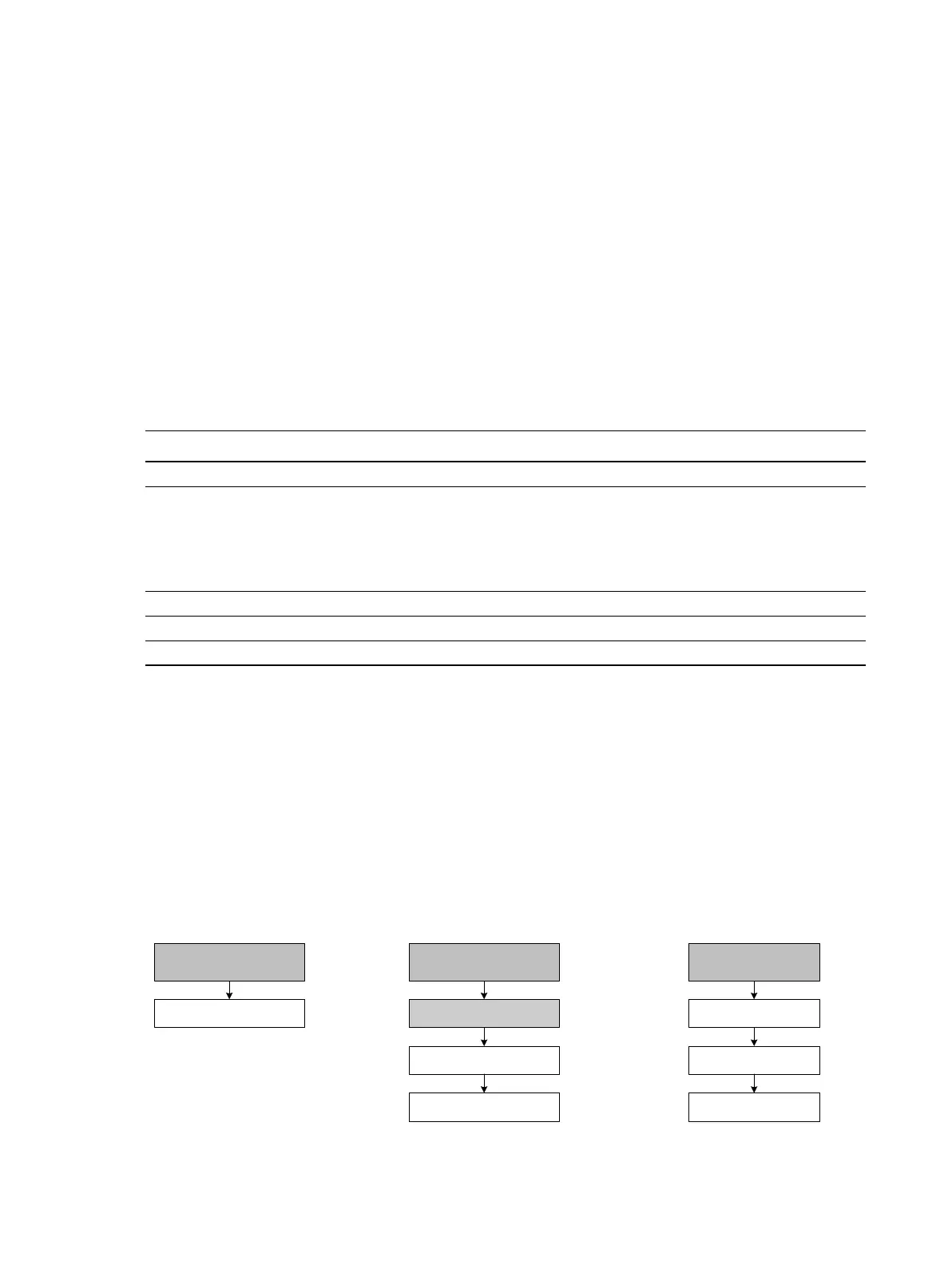
To configure the frequency output, see the menu flowcharts in Figure 6-6. For details on frequency
output parameters, see Sections 6.6.1 through 6.6.5.
Note: If you use the display to configure the frequency output, you can configure only the process
variable and the parameters used by the Frequency = Flow scaling method. To configure other
frequency output parameters, use ProLink II or the Communicator.
Figure 6-6 Configuring the frequency output
Table 6-11 Frequency output configuration parameters
Parameter name
ProLink II Communicator Display
Tertiary variable TV SRC
Scaling method
• Freq = flow
• Freq factor
(1)
• Rate factor
(1)
• Pulses/unit
• Units/pulse
(1) Displayed only if Scaling Method is set to Freq = Flow.
FO scale method
•Freq = flow
• TV freq factor
(1)
• TV rate factor
(1)
• TV pulses/unit
• TV units/pulse
Not applicable
Freq pulse width Max pulse width Not applicable
Freq output polarity FO polarity POLAR
Freq fault action FO fault indicator Not applicable
IO
CH B
Off-line maint >
Off-line config
Set FO
Frequency
ProLink >
Configuration>
1 Channel setup
5 FO setup
On-Line Menu >
5 Detailed Setup
3 Config outputs
Communicator DisplayProLink II