G3SeriesPROFIBUS‐DPTechnicalManual
Page 12
TDG3PTTM1-2EN 02/09
Subject to change without notice
www.numatics.com/g3
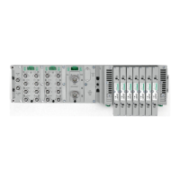
Communication Module Description
Detail No. Description
1 “Set” Button – used to navigate through user menus and to set parameters
2 Module Status LED
3 5 Pin M12 Reverse Key Male Communication Connector
4 5 Pin M12 Reverse Key Female Communication Connector
5 Mounting Hole
6 “Next” Button – used to navigate through user menus and to set parameters
7 Graphic Display – used to display parameter information
8 Network Status LED
9 Slot for text ID tags
10 Keying for preventing I/O module insertion
11 5 Pin MINI Male Power Connector
7
10
9
8
3
11
5
1
2
6
4

 Loading...


