ROC800-Series Instruction Manual
4-24 Input/Output Modules Revised July-2017
Figure 4-29. MVS I/O Field Wiring
Note: A “star” configuration for transmitters may not be reliable.
Terminations are recommended for long distances (greater that 1000
meters) at the extreme ends of the circuit. Terminate the two outermost
devices to reduce signal reflection in the circuit. The MVS termination
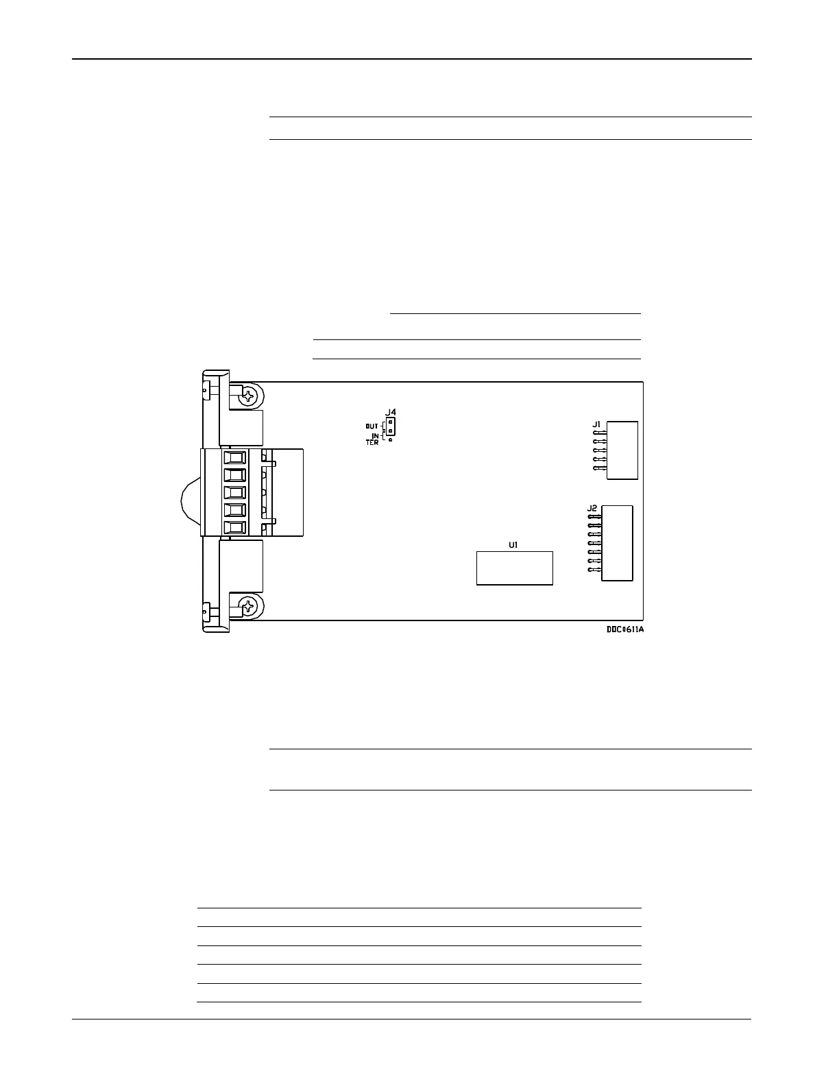
jumper is located at J4 on the module. Refer to Table 4-4 and Figure 4-
30.
Table 4-4. MVS Termination
Figure 4-30. MVS Jumper J4 (Shown Not Terminated)
Four wires run from the MVS module terminal block and connect to the
sensor. The wires should be a minimum size of 22 AWG and a
maximum length of 1220 m (4000 ft).
Note: Insulated, shielded, twisted-pair wiring is required when using
MVS signal lines.
Two of the terminal blocks provide power and the other two terminals
provide a communication path. Table 4-5 identifies the terminals.
Table 4-4. MVS Signal Routing
Lit green when transmitting