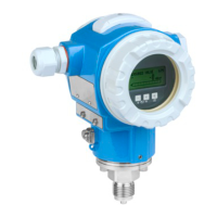
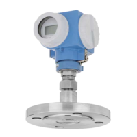
Cerabar M, Deltabar M, Deltapilot M Commissioning with the FF configuration program
Endress+Hauser 139
4. Load Cff and device description files into the host system or the configuration program.
Make sure you are using the right system files.
5. Identify the device using the DEVICE_ID (see Point 2). Assign the desired tag name
to the device by means of the "Pd-tag/FF_PD_TAG" parameter.
Configuring the Resource Block
1. Open the Resource Block.
2. If necessary, disable the lock for device operation. ä 54, Section 6.3.5 "Locking/
unlocking operation". Operating is unlocked as standard.
3. If necessary, change the block name. Factory setting: RS-xxxxxxxxxxx (RB2) ()
4. If necessary, assign a description to the block by means of the "Tag Description/
TAG_DESC" parameter.
5. If necessary, change other parameters as per the requirements.
Configuring the Transducer Blocks
The device has the following Transducer Blocks:
• Pressure Transducer Block
• DP_FLOW Block (Deltabar)
• Display Transducer Block
• Diagnostic Transducer Block
The explanation that follows is an example for the Pressure Transducer Block.
1. If necessary, change the block name. Factory setting: TRD1_xxxxxxxxxxx (PCD)
2. Set the block mode to OOS by means of the "Block Mode/MODE_BLK", TARGET element.
3. Configure the device in accordance with the measuring task. See also these
Operating Instructions Section 8.2 to Section 9.3.
4. Set the block mode to "Auto" by means of the "Block Mode/MODE_BLK" parameter,
TARGET element.
Note Dependencies when setting parameters!
‣ The block mode must be set to "Auto" for the Pressure and DP_FLOW Block (Deltabar) for
the measuring device to function correctly.
Configuring the Analog Input Blocks
The device has 2 Analog Input Blocks that can be assigned as required to the various process
variables.
1. If necessary, change the block name. Factory setting: AI1_xxxxxxxxxxx (AI)
2. Set the block mode to OOS by means of the "Block Mode/MODE_BLK" parameter,
TARGET element.
3. Use the "Channel/CHANNEL" parameter to select the process variable which should be
used as the input value for the Analog Input Block. The following settings are possible:
Cerabar and Deltapilot:
– Channel/CHANNEL = 1: Primary value, a pressure or level value depending on the
measuring mode selected
– Channel/CHANNEL = 2: Secondary value
– Channel/CHANNEL = 3: Pressure
– Channel/CHANNEL = 4: Max. pressure
– Channel/CHANNEL = 5: Level before linearization
Factory setting:
– Analog Input Block 1: Channel/CHANNEL = 1: Primary Value (primary measured
value)
– Analog Input Block 2: Channel/CHANNEL = 2: Secondary Value (sensor temperature)

 Loading...
