Installation Cerabar M, Deltabar M, Deltapilot M
24 Endress+Hauser
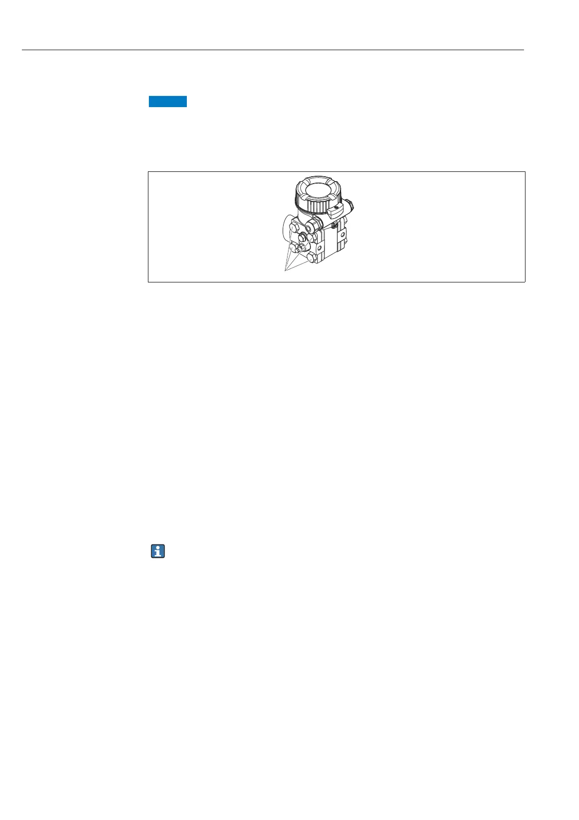
4.6 Installing Deltabar M
Incorrect handling!
Damage of the device!
‣ Disassembly of the screws with item number (1) is not permissible under any
circumstances and will result in loss of warranty.
4.6.1 Installation position
• Due to the orientation of the Deltabar M, there may be a shift in the measured value, i.e.
when the container is empty, the measured value does not display zero. You may correct
this zero point shift by a position adjustment in one of the following ways:
– via the operation keys on the electronics module ( ä 47, "Function of the operating
elements")
– via the operating menu ( ä 73, "Pos. zero adjust")
• General recommendations for routing the impulse piping can be found in DIN 19210
"Methods for measurement of fluid flow; differential piping for flow measurement devices"
or the corresponding national or international standards.
• Using a three-valve or five-valve manifold allows for easy commissioning, installation and
maintenance without interrupting the process.
• When routing the impulse piping outdoors, ensure that sufficient anti-freeze protection is
used, e.g. by using pipe heat tracing.
• Install the impulse piping with a monotonic gradient of at least 10%.
• Endress+Hauser offers a mounting bracket for installing on pipes or walls ( ä 29, "Wall
and pipe-mounting (option)").
Installation position for flow measurement
For more information about differential pressure flow measurement refer to following
documents:
• Differential pressure flow measurements with orifices: Technical Information TI00422P
• Differential pressure flow measurement with Pitot tubes: Technical Information TI00425P