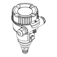
Ceraphant PTP31B, PTP33B Description of device parameters
Endress+Hauser 49
13 Description of device parameters
13.1 Switch output 1 and switch output 2
13.1.1 Hysteresis (Switch point and switchback point)
SP1/SP2 switch point value, output 1/2
RP1/RP2 switchback point value, output 1/2
Navigation SP1/SP2
RP1/RP2
Note The hysteresis is implemented using the "SP1/SP2" and "RP1/RP2" parameters. Since the
parameter settings depend on one another, the parameters are described all together.
• SP1 = switch output 1
• SP2 = switch output 2 (optional)
• RP1 = switchback point 1
• RP2 = switchback point 2 (optional)
1
2
0
SP1/SP2
RP1/RP2
0
HNO
p
t
1
HNC
A0022943
3 SP1/SP2: switch point 1/2; RP1/RP2: switch-back point 1/2
0 0-signal. Output open in quiescent state.
1 1-signal. Output closed in quiescent state.
2 Hysteresis
HNO Closing
HNC NC contact
Description The switch point "SP1/SP2" and the switchback point "RP1/RP2" can be defined with these
functions (e.g. for pump control).
When the set switch point "SP1/SP2" is reached (with increasing pressure), an electrical
signal change takes place at the switch output.
When the set switchback point "RP1/RP2" is reached (with decreasing pressure), an
electrical signal change takes place at the switch output.
The difference between the value of the switch point "SP1/SP2" and the switchback point
"RP1/RP2" is known as the hysteresis.
 Loading...


