Installation Micropilot FMR10
18 Endress+Hauser
NOTICE
There is no conductive connection between the mounting bracket and transmitter
housing.
Electrostatic charging possible.
‣
Integrate the mounting bracket in the local potential equalization system.
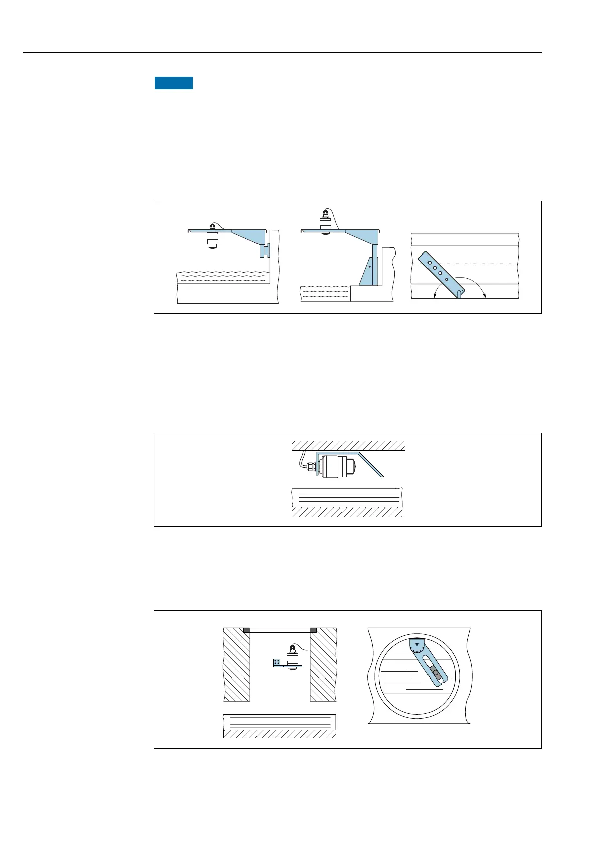
5.1.10 Cantilever installation, with pivot
The cantilever, wall bracket and mounting frame are available as accessories.
A0028412
12 Cantilever installation, with pivot
A Cantilever with wall bracket
B Cantilever with mounting frame
C Cantilever can be turned (e.g., in order to position the device over the center of the flume)
5.1.11 Installation of horizontal mounting bracket for sewer shafts
The horizontal mounting bracket for sewer shafts is available as an accessory.
A0037747
13 Installation of horizontal mounting bracket for sewer shafts
5.1.12 Mounting in a shaft
The pivoted mounting bracket is available as an accessory.
A0037748
14 Mounting in a shaft, pivotable and adjustable
A Arm with wall bracket
B Pivotable and adjustable arm (e.g. to align the device with the center of a channel)

 Loading...


