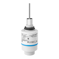
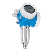
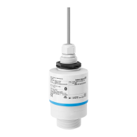
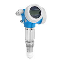
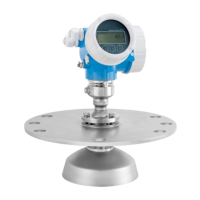
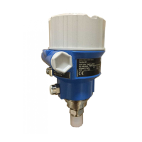
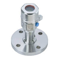
Micropilot FMR20 HART Technical data
Endress+Hauser 63
14 Technical data
14.1 Input
Measured variable The measured variable is the distance between the reference point and the product
surface.
The level is calculated based on E, the empty distance entered.
Measuring range Maximum measuring range
10 m (32.8 ft)
Installation requirements
• No agitators
• No buildup
• Relative dielectric constant ε
r
> 2
Contact Endress+Hauser for lower ε
r
values
Usable measuring range
The usable measuring range depends on the medium's reflective properties, the
installation position and any possible interference reflections.
Optimum results are achieved with coarse-grained material and the use of the flooding
protection tube.
Reduction of the max. possible measuring range by:
• Media with bad reflective properties (= low ε
r
value)
• Product cone
• Extremely loose surfaces of bulk solids, e.g. bulk solids with low bulk weight in the case
of pneumatic filling.
• Formation of buildup, particularly of moist products.
For dielectric constants (DC values) of many media commonly used in various
industries refer to:
• the Endress+Hauser DC manual (CP01076F)
• the Endress+Hauser "DC Values App" (available for Android and iOS)
Operating frequency K-band (~ 26 GHz)
Transmission power Mean power density in the direction of the beam
• At a distance of 1 m (3.3 ft): < 12 nW/cm
2
• At a distance of 5 m (16 ft): < 0.4 nW/cm
2
14.2 Output
Output signal 4 to 20 mA
An 4 to 20 mA interface is used for measured value output and to power to the device.
Digital output HART®
• Signal encoding; FSK ±0.5 mA over current signal
• Data transmission rate;1 200 Bit/s

 Loading...
