Micropilot FMR56, FMR57 FOUNDATION Fieldbus Installation
Endress+Hauser 27
Antenna
1)
Maximum nozzle height H
max
2)
BC: Horn 80mm/3" 260 mm (10.2 in)
BD: Horn 100mm/4" 480 mm (18.9 in)
1) Feature 070 of the product structure
2) valid for antennas without antenna extension
Please contact Endress+Hauser for applications with higher nozzle.
Threaded connection
For devices with a threaded connection it may be necessary - depending on the antenna
size - to unmount the horn before fastening the device and to mount it again afterwards.
• Tighten with the hexagonal nut only.
• Tool : 60 mm hexagonal wrench
• Maximum permissible torque: 60 Nm (44 lbf ft)
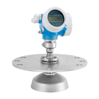
6.3.4 Parabolic antenna (FMR57)
Alignment
Ideally, the parabolic antenna should be installed vertically. To avoid interference reflections
or for optimum alignment within the vessel, the Micropilot with optional alignment device
can be swiveled by 15° in all directions .
Nozzle mounting
• Case 1: Ideally, the parabolic antenna should protrude from the nozzle (1). Particularly
when using the alignment device, please ensure that the parabolic reflector is protruding
from the nozzle/roof so as not to inhibit alignment.
• Case 2: For applications with higher nozzle it may be necessary to install the parabolic
antenna completely in the nozzle (2).
The maximum height of the nozzle (H
max
) to the parabolic mirror should not exceed
500 mm (19.7 in). Interfering edges within the nozzle should be avoided.
 Loading...


