Wiring Solicap M FTI55, FTI56
42 Endress+Hauser
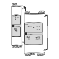
4.7 Connecting the electronic insert FEI52 (DC PNP)
The three-wire DC connection should, wherever possible, be connected as follows:
• To programmable logic controllers (PLCs),
• to DI modules in accordance with EN 61131-2
A positive signal is present at the switch output of the electronic system (PNP).
Power supply
Supply voltage: 10 to 55 V DC
Ripple: max. 1.7 V; 0 to 400 Hz
Current consumption: < 20 mA
Power consumption without load: max. 0.9 W
Power consumption with full load (350 mA): 1.6 W
Reverse polarity protection: yes
Separation voltage: 3.7 kV
FEI52 overvoltage protection: overvoltage category II
Signal on alarm
Output signal on power failure or in the event of device failure: I
R
< 100 μA
Connectable load
• Load switched via transistor and separate PNP connection, max. 55 V
• Load current max. 350 mA (cyclical overload and short-circuit protection)
• Residual current < 100 μA (with transistor blocked)
• Capacitive load max. 0.5 μF at 55 V; max. 1.0 μF at 24 V
• Residual voltage < 3 V (for transistor switched through)
Connect the FEI52 (DC PNP) as follows:
1. Make the connection as shown in the graphic.
2. Turn the cable gland until tight.
3. Set the function switch to position 1
(operation).
!
Note!
Do not switch on the supply voltage until you have
familiarized yourself with the device functions as
described on Page 49 "Operation". This will ensure
that you do not accidentally trigger any processes by
switching on the supply voltage.
4. Switch on the supply voltage.
* R = External load (I
max.
350 mA, U
max
55 V DC)
TI418F42

 Loading...