29
© 2017 Energreen Srl
Professional machinery
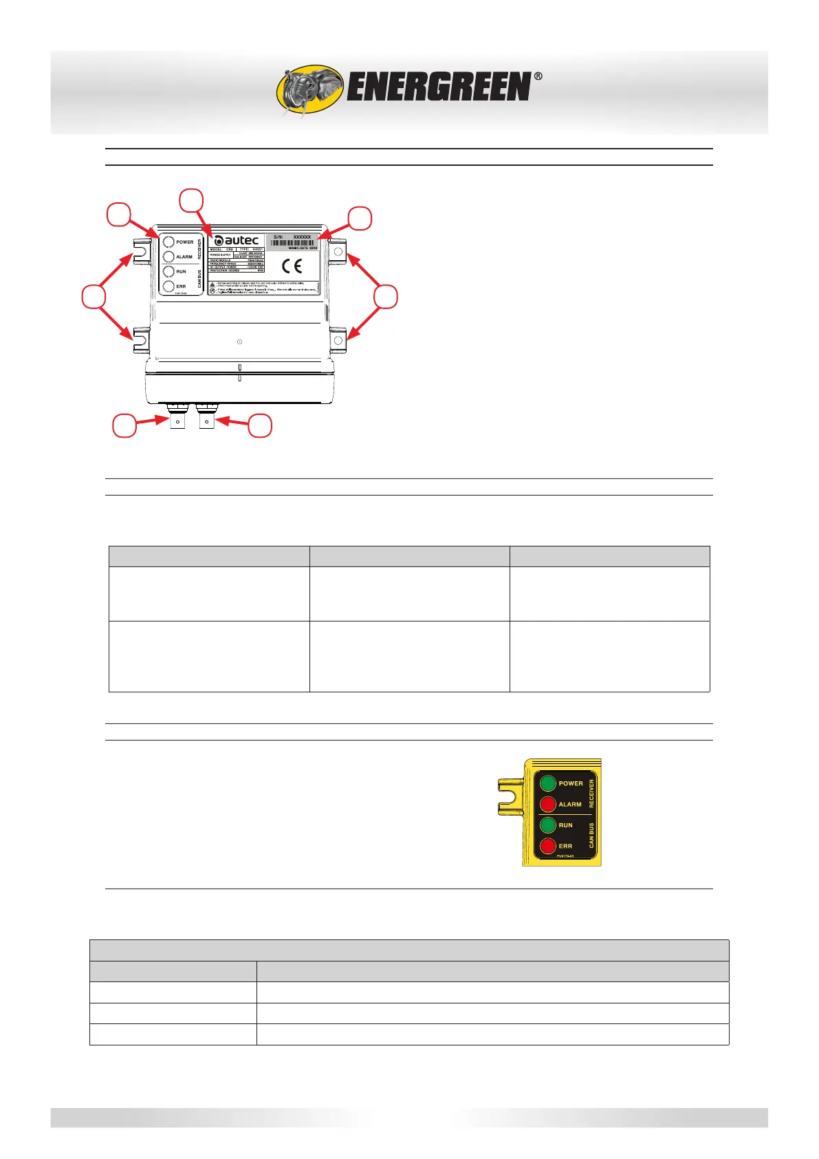
6.3.1 - RECEIVER DESCRIPTION
A A
C
D
EF
B
A - Mounting holes
B - LED
C - Rating plate
D - Remote control unit identication plate
E - Connector A
F - Connector B
6.3.2 - RECEIVER IDENTIFICATION PLATES
The following plates are on the receiver unit:
Plate Position Information contained
Remote control unit identica-
tion plate
This is found on the casing of
the receiver unit on the con-
nectors side:
The serial number of the
remote control, a bar code and
the year of manufacturer.
Rating plate This is found on the left-hand
side of the casing.
The MODEL, TYPE and main
technical data of the receiver,
the markings and any remote
control trademarks.
6.3.3 - RECEIVER LIGHT SIGNALS
The remote control unit feature four LEDs:
• POWER green
• ALARM red
• RUN green
• ERR red
POWER LED (GREEN)
The POWER LED indicates the status of the receiver unit and the radio-electric connection.
POWER LED
SIGNAL Meaning
Off The receiving unit is off.
Access The receiving unit is powered up and there is no radio-electric connection
Flashing The receiving unit is powered up and there is a radio-electric connection

 Loading...