Digital Servo Controllers
DSV 130 / DSV 132 / DSV 133
Operating Manual Rev. 1.8 www.engelantriebe.de Page 15
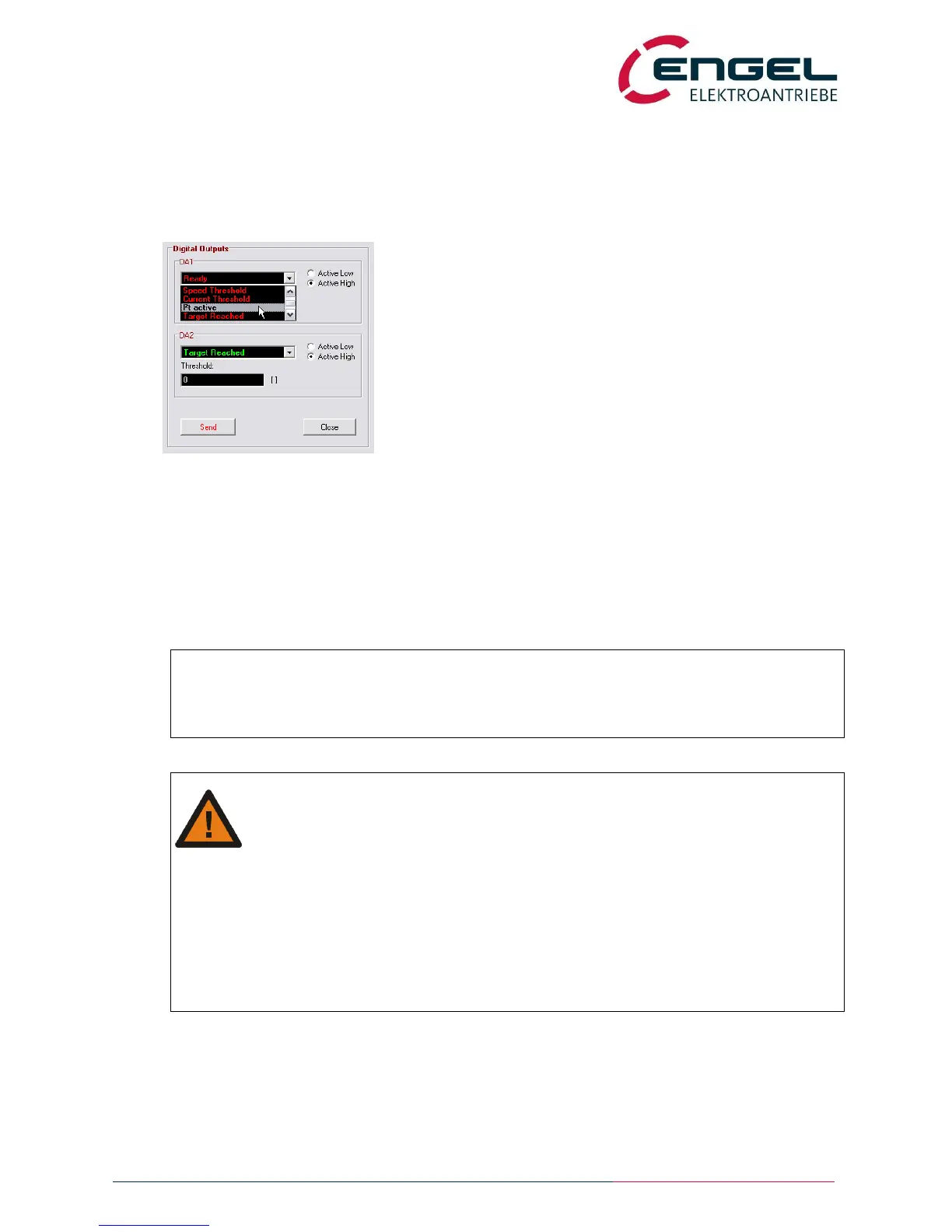
4.4.3 Digital outputs
The function of the digital outputs DO1 and DO2 is configurable in the menu OPTIMISATION / DIGITAL OUTPUTS
(see the DSerV software):
Active low/high Defines the outputs polarity
Enable Shows the actual enable -state.
Speed threshold Active when the actual speed > threshold speed
Current threshold Active when the actual current > threshold current.
I²t active Active when the I
2
t limitation is active
Target reached Active after a positioning process is successfully
concluded.
Ready Active when the controller is error-free
Following error Active when the actual following error > threshold
value.
4.4.4 Parking brake
The DSV13x features the triggering of an electromagnetic parking brake. Connected to X2, the parking brake will
be automatically switched depending of the drives enable state. The parking brake is switched without any time
delay.
Notice:
To prevent abrasion at an early stage mind the following:
- Avoid switching enable with an abruptly rising torque.
- Disable the drive preferably at standstill
Attention!
Operating voltage of the parking brake = intermediate circuit voltage!
The voltage at X7/Pin1 is equivalent to the positive intermediate circuit voltage. Before
connecting a parking brake, make sure the voltage supply of the parking brake is equal to the
intermediate circuit voltage.
When using a permanent magnet parking brake:
- Take notice of polarity
- Exceeded intermediate circuit voltage can reduce the braking effect.
Parking brakes with a current consumption 1500mA can be connected directly. Brakes with a
higher current consumption have to be supplied separately. The output of the DSV can be used to
control a relais.
 Loading...