Digital Servo Controllers
DSV 130 / DSV 132 / DSV 133
Operating Manual Rev. 1.8 www.engelantriebe.de Page 22
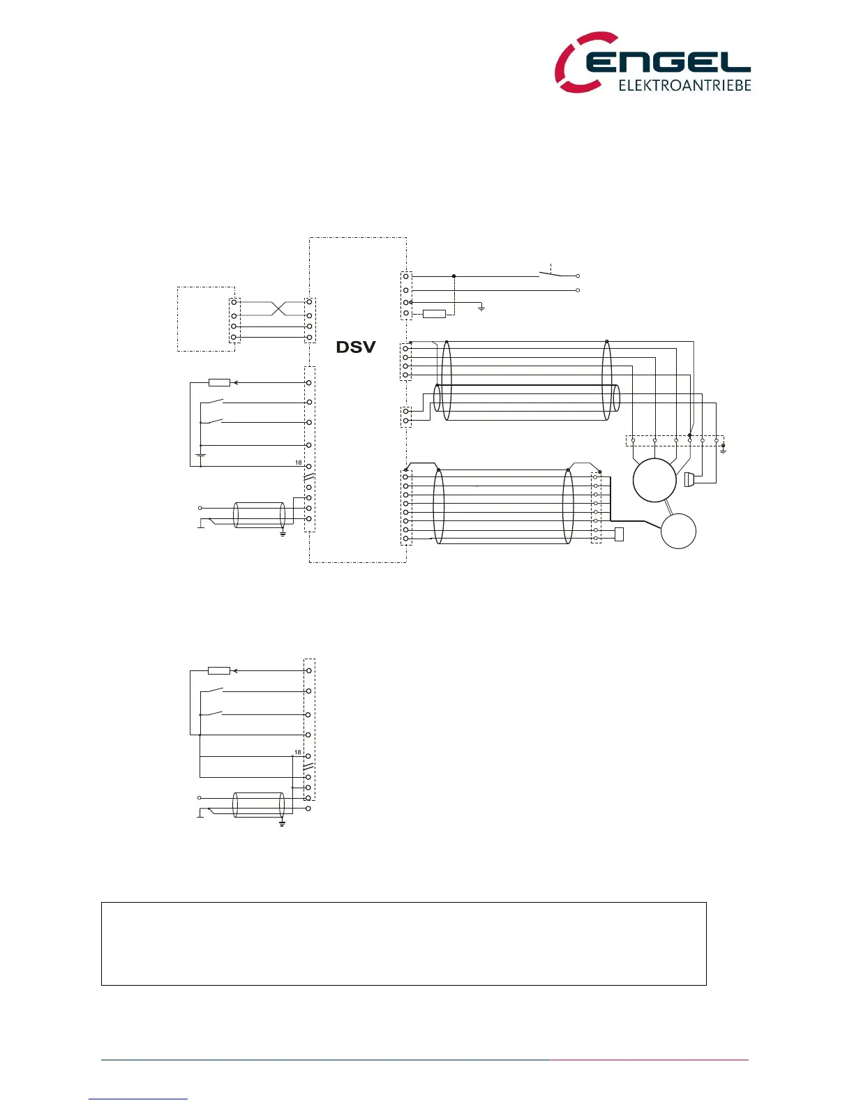
6.2 Installation diagram
The devices DSV130, DSV132 and DSV133 can either operate with brushless three-phase synchronous motors or brush-
type DC motors.
The following diagrams are only two examples of configuration and do not represent all possibilities of wiring.
6.2.1 Operating with a three-phase synchronous motor
fig.: Installation diagram for a three-phase synchronous motor
Notice:
When connecting ENGEL BL motors, phases U and W have to be interchanged!
X1
U
V
W
1
2
3
4
PE
PE
+24VDC (48VDC@DSV132)
X2
+Ub
GND / 0V
PE
1
2
3
resolver
*1) X4 shown uncomplete.
S4
S2
R1
S3
7
1
6
4
9
3~
2
3
4
6
7
MT+
MT-
R2
5
8
5
8
PTC
X3
2
3
5
GND
X5
Rx
Tx
2
3
5
COM
(9pol)
PC,
Laptop
installation example: using internal voltage +U_H:
Attention: No galvanic isolation of digital inputs and outputs !
S1
2 1
labels shown of connector ASTA 035... Intercontec
M
U V W
PE
U
V
W
*2) connectio to +U_EA only necessary when using digital outputs
X4
*1)
AE1+
AE1-
GND_EA
1
2
setpoint input
±10V
+
15...30V
controller enable
DE1
+U_H
GND_H
16
4
+U_EA
DA1
digital output
22
19
6
max 50mA
*2)
X4
*1)
AE1+
AE1-
GND_EA
1
2
setpoint input
±10V
controller enable
DE1
+U_H
GND_H
16
4
+U_EA
DA1
digital output
22
19
6
max 10mA
*3)
*2)
*3) reduced output current when using +U_H
130
132
(+UZK) BR+
BR-
1
2
A
B
parking brake
+ -
PE
T
0V
(external brake resistor, optional)
R
X7
power stage enable
DE2
13
4
6
DSR
DE2
power stage enable
13
 Loading...