Digital Servo Controllers
DSV 130 / DSV 132 / DSV 133
Operating Manual Rev. 1.8 www.engelantriebe.de Page 23
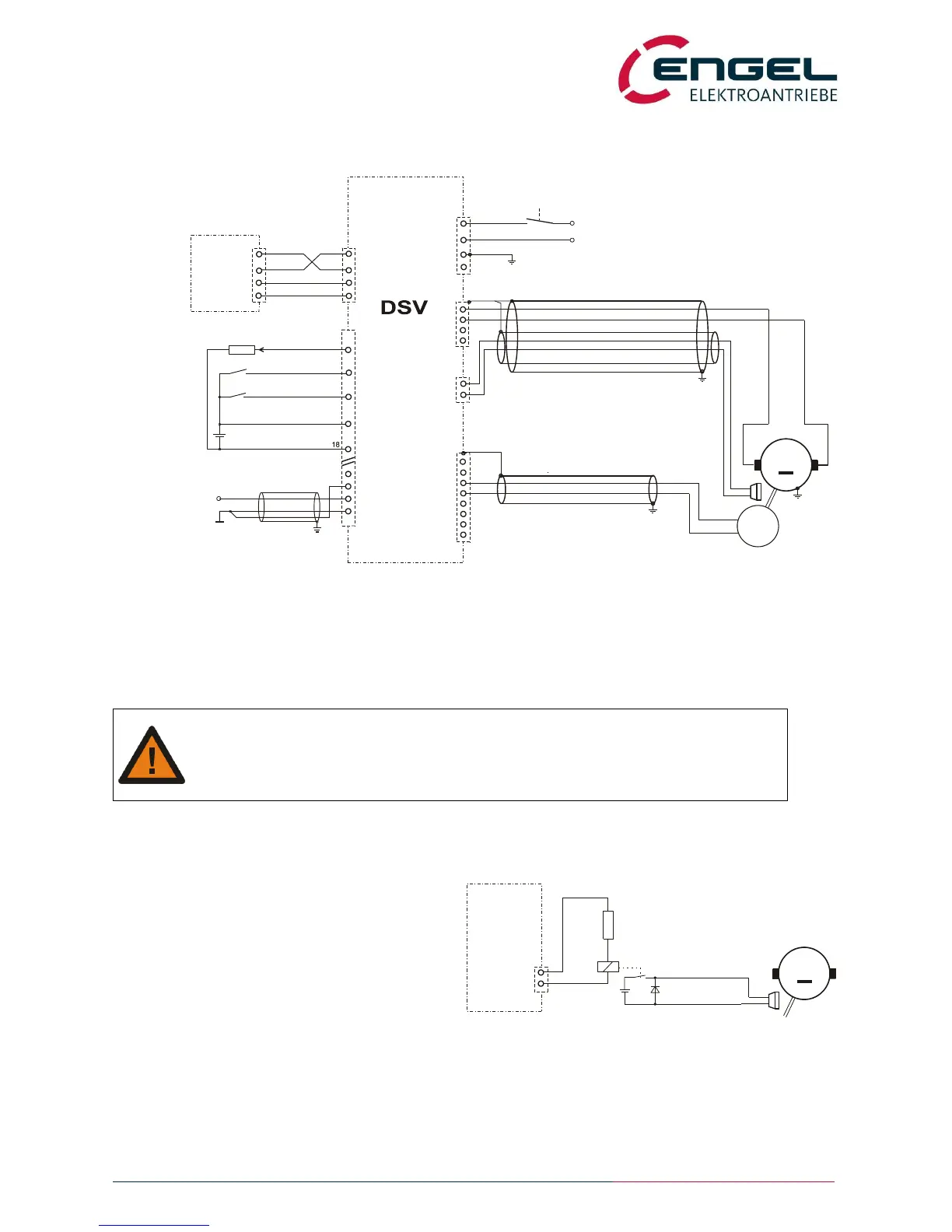
6.2.2 Operating with a DC motor
fig.: Installation diagram for a DC motor
The diagram shows the setup with a DC tacho for speed feedback.
Attention!
Rated voltage of the parking brake = intermediate circuit voltage Here: 42V x 2 = 60V !
6.2.3 Decoupling of the parking brake
If the rated voltage value of the parking brake is
unequal to the intermediate voltage value, the
parking brake has to be supplied by an external
voltage source and controlled by a relay.
K1: rated voltage, if possible intermediate voltage
value
R: To compensate possible differences of the
voltage K1
D: free wheeling diode
fig.: Decoupling of the parking brake
X1
U
V
W
1
2
3
4
PE
PE
42VAC
X2
+Ub
GND / 0V
PE
1
2
3
T
Tacho
*1) X4 shown uncomplete.
Tacho+
Tacho-
R1
S3
7
1
6
4
9
MT+
MT-
R2
5
8
X3
2
3
5
GND
X5
Rx
Tx
2
3
5
COM
(9pol)
PC,
Laptop
S1
2
*2) connection to +U_EA only necessary when using digital outputs
X4
*1)
AE1+
AE1-
GND_EA
1
2
setpoint input
±10V
+
15...30V
controller enable DE1
+U_H
GND_H
16
4
+U_EA
DA1
digital output
22
19
6
max 50mA
*2)
133
(+UZK) BR+
BR-
1
2
parking brake
+
-
PE
T
*3) external brake resistor not applicable with AC supply
X7
power stage enable
DE2
13
4
6
DSR
5V/1000min
-1
M
+
-
*3)
Tacho-
Tacho+
(+UZK) BR+
BR-
1
2
X7
parking brake
+
-
M
+
-
K1
R
+
24V
DSV13x
D
 Loading...