Digital Servo Controllers
DSV 130 / DSV 132 / DSV 133
Operating Manual Rev. 1.8 www.engelantriebe.de Page 31
Step 6: Increase the proportional gain by a few hundredths, enable the drive and judge speed vs. time curve again.
Increase the gain until the drive starts to oscillate. Then reduce the gain until the oscillation is not visible
anymore.
For optimum control, reduce the time constant until the speed set value is reached with one single
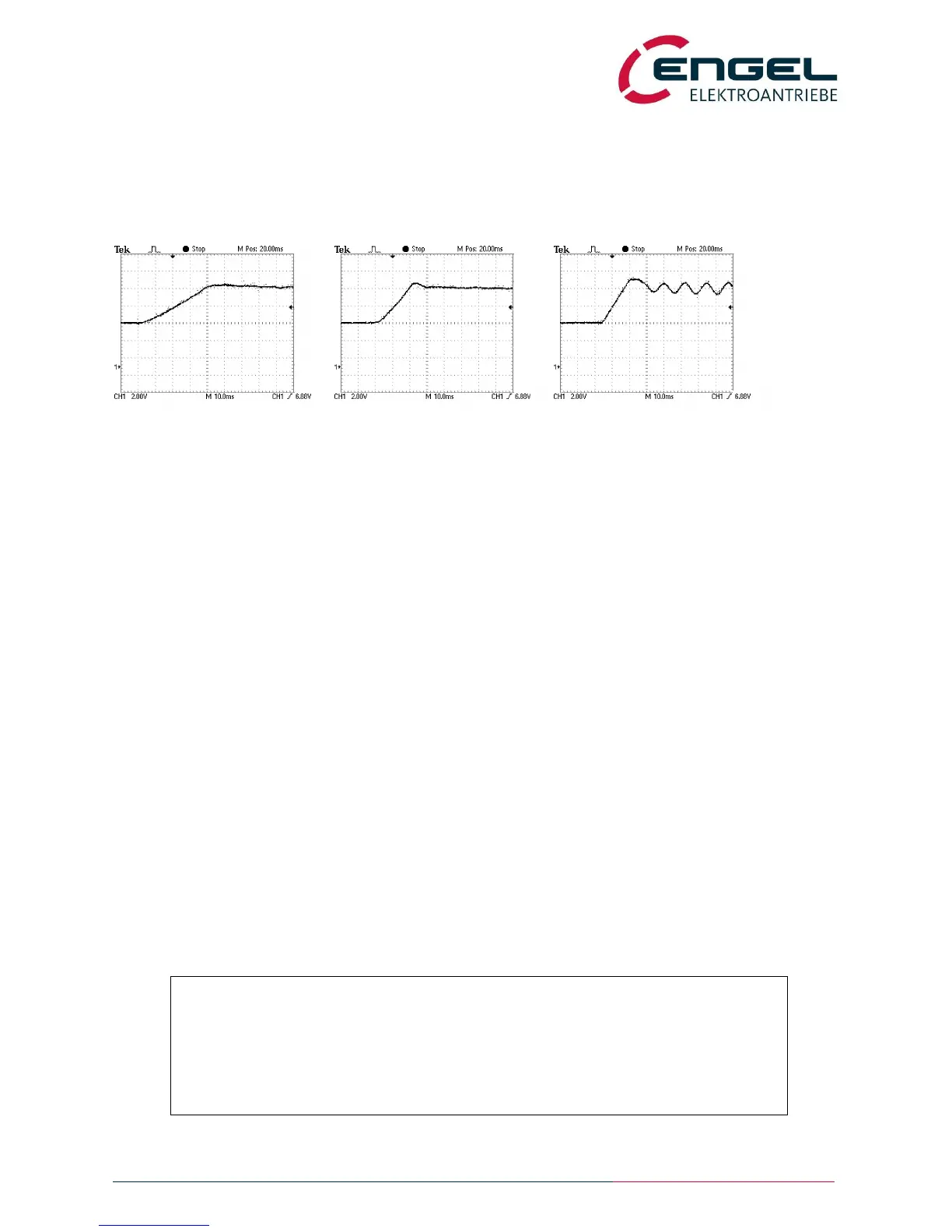
overshoot of approximately 4-10%. See also diagrams below:
a) gain too low b) ideal gain / time constant c) gain too high
time constant too high time constant too low
fig.: speed step-responses with varying speed controller parameters
9.3.2 Tuning of DC motors with BEMF control and IxR compensation
Step 1: Drive completely installed, wired and fully operational according to the set-up notes in chapter 7.
Step 2: Make sure that the rated and maximum current are set correctly and the current controller is properly tuned.
If needed, adjust the current controller as described in chapter 9.1.
Step 3: The voltage constant and the terminating resistance of the motor are assigned in DSerV under
OPTIMISATION / MOTOR.
The voltage constant is normally given in the datasheet. It can be estimated mathematically:
k
e
= (U
N
– I
N
x R
A
– 2V) / n
N
x 1000 where: U
N
= rated voltage
I
N
= rated current
R
A
= amature resistance
n
N
= rated speed
Example:
GNM 5480 24V 3000min
-1
with: I
N
=12.9A R
A
=0.106
k
e
= 24V – 12.9A x 0.109Ohm / 3000min-1 * 1000 = 7.5 V/1000min
-1
The terminal resistance of the motor is also given in the data sheet.
Notice:
Assigning the voltage constant and the terminal resistance as specified in the
datasheet does not necessarily guarantee the ideal configuration for the controller.
Typically, the IxR compensation has to be estimated by the value of the terminal
resistance.
Smaller terminal resistance values prevent oscillation!