Digital Servo Controllers
DSV 130 / DSV 132 / DSV 133
Operating Manual Rev. 1.8 www.engelantriebe.de Page 18
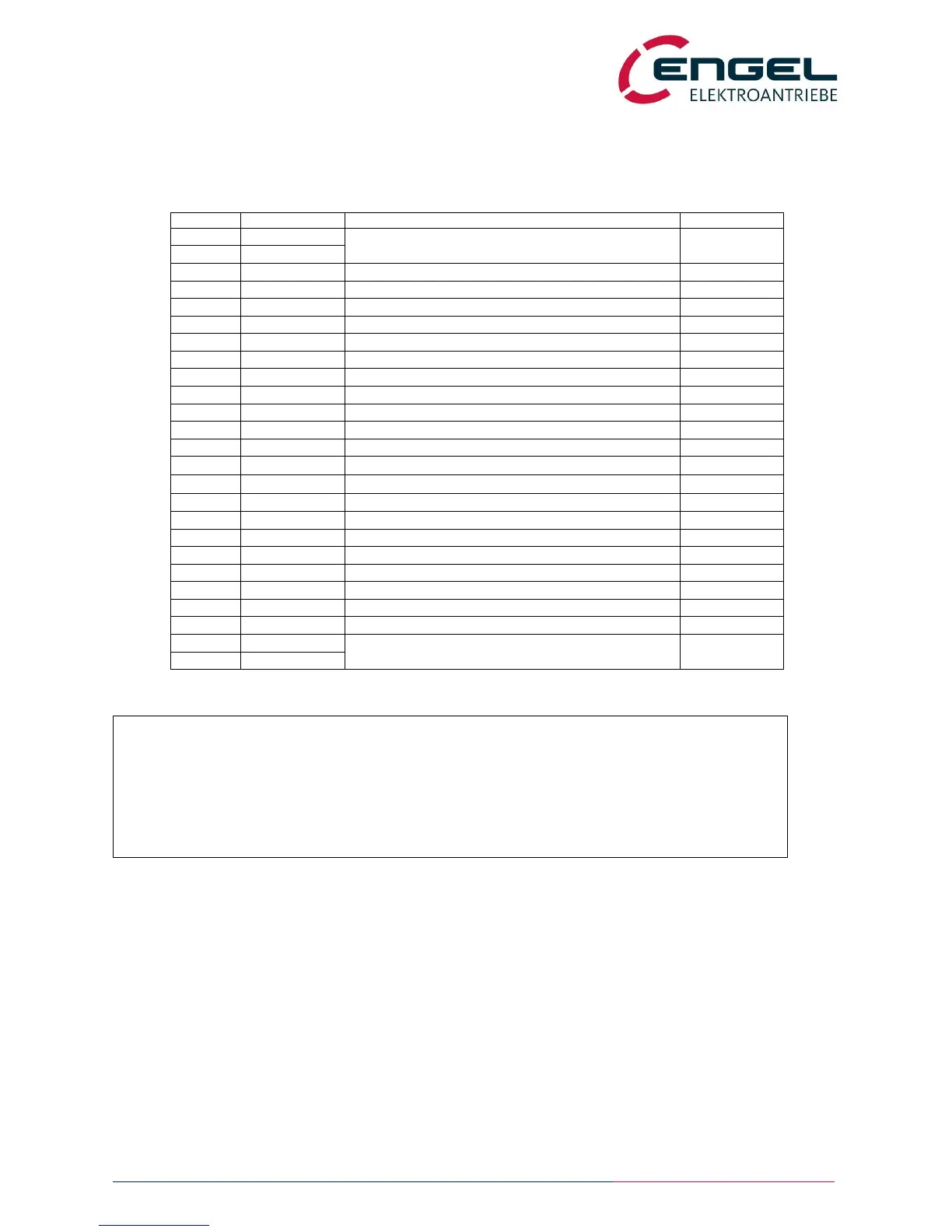
5.4 X4 – Set values connector
device side connector: 25 – pole D-SUB (female)
cable side connector: 25 – pole D-SUB (male)
analogue input 1 (differential input)
analogue input 2 (ground supply = GND_H)
auxiliary voltage +24V (voltage source)
digital input 8 (position prefix bit 1/inverted set value)
digital input 7 (position prefix bit 0/ set value=0)
digital input 5 (limit switch left)
digital input 4 (limit switch right)
digital input 3 (start positioning)
analogue output 1 (device monitoring)
analogue output 2 (device monitoring)
reference potential for auxiliary voltage (pin 4)
separate reference potential for the I/O’s
digital input 9 (position prefix bit 2)
digital input 10 (position prefix bit 3)
digital output 1 (configurable)
digital output 2 (configurable)
Notice:
There is a galvanic isolation between the digital inputs / outputs and the control unit. The
potential references of the I/O’s are +U_EA (X4.6) and GND_EA (X4.18). In case that no
external control voltage is available, the internal auxiliary voltage can be used to excite the inputs
and/or to supply the digital outputs. In that case, connect +UH (X4.4) with +U_EA (X4.6), as
well as GND_H (X4.16) with GND_EA (X4.18). The galvanic separation is thus cancelled!
 Loading...