Digital Servo Controllers
DSV 130 / DSV 132 / DSV 133
Operating Manual Rev. 1.8 www.engelantriebe.de Page 26
8 Status indicator, error codes
The DSV13xs status indicator shows clearly the operating status of the drive. Each of the two pairs of LED’s
(green and red) show the status of the drive, respectively of the CAN interface. The red and green LED may show
the following states of the drive:
Device without function:
- Check supply voltage
- Especially when USB-RS232 converters are used:
disconnect RS232 and switch on the power supply
again after a short delay time.
The servo-controller DSV13x is equipped with an error register in order to detect and display even momentary
errors, such as over-current.
An error causes the switch-off of the power stage and the motor drops out. Drive errors are indicated by the drive
red LED as a blinking code with the number of light pulses representing the error code. The table of error codes
allows to determine the error and to find a remedy. In case of multiple errors, only the one with the highest priority
is reported. The PC software DSerV shows the cause of the error in plain text.
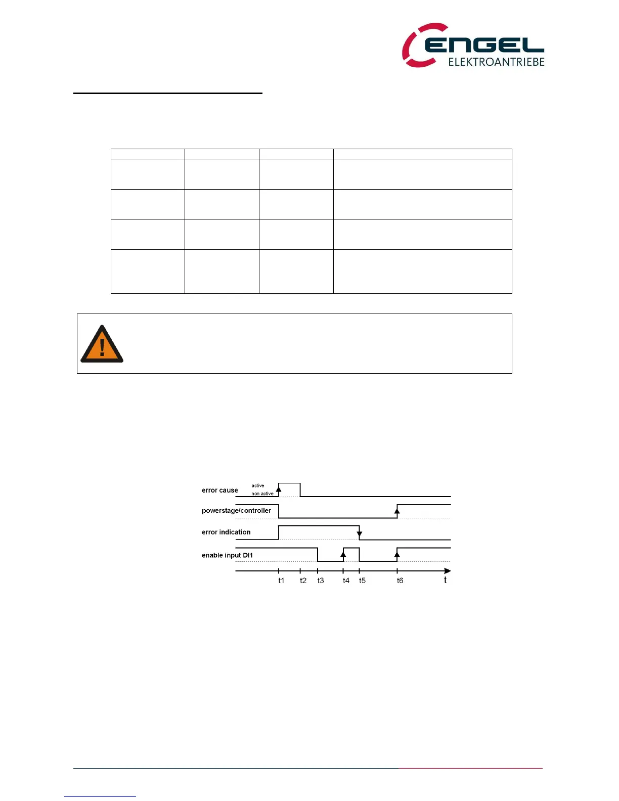
After removing the cause of the error, the drive becomes operational again by changing the enable input from
“OFF” to “ON”. The powerstage will only be enabled after a second change from “OFF” to “ON”.
fig.: error logic
t1: Occurrence of an error: powerstage disabled, error indication active
t2: Cause of error relieved
t3: User sets enable input to off
t4: User sets enable input to on (1
st
OFF-ON-transition): powerstage / controller remain disabled
t5: User sets enable input to off. Error indication is reset as error is removed, ready relay is switched on.
t6: User sets enable input to on (2
nd
OFF-ON-transition): power stage and controller enabled
Switching the DSV mains supply off and on does also reset the error indication.
Notice: The error 10 “internal error” is not resettable with the enable input.