Digital Servo Controllers
DSV 130 / DSV 132 / DSV 133
Operating Manual Rev. 1.8 www.engelantriebe.de Page 17
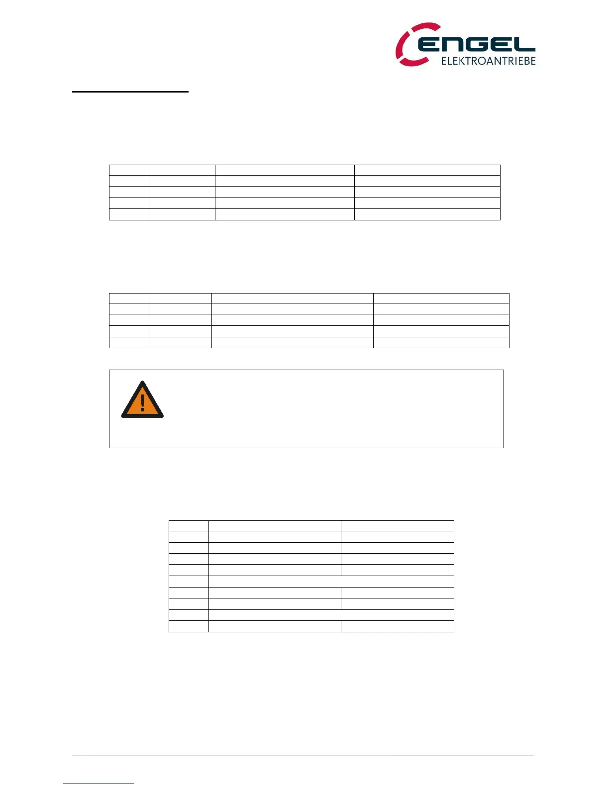
5 Pin assignment
5.1 X1 – Motor connection
device side connector: 4-pole power- combicon (7,62mm)
cable side connector 4-pole plug (Phoenix PC 5/4-STF-SH-7,62)
5.2 X2 – Voltage supply
device side connector: 4-pole power- combicon (7,62mm)
cable side connector 4-pole plug (Phoenix PC 5/4-STF-SH-7,62)
Supply +24V (+48V@DSV132)
connector for external brake resistor
Warning concerning DSV133!
Do not connect the alternating voltage supply to protective earth!
Connections between ac voltage supply and protective earth can cause damage to
components connected to the DSV133, if they have a separate connection to
protective earth (e.g. PC with GND-PE connection)
5.3 X3 – Motorsignals
device side connector: 9 – pole D-SUB (female)
cable side connector: 9 – pole D-SUB (male)
temperature probe motor +
temperature probe motor –
*1) Connecting an external brake resistor is not possible for the DSV133.
*2) When using an analogue tacho (for DC motors), the tacho input has to be activated by setting the Jumpers JP1
and JP2 in the inside of the DSV13x.

 Loading...