208
WSG-1068 COOLING SYSTEM
Radiator Leak Test, Removed From
Vehicle
CAUTION: Never leak test an aluminum
radiator in the same water that copper/brass
radiators are tested in. Flux and caustic cleaners
may be present in the cleaning tank and they will
damage aluminum radiators.
1. Always install plugs in the oil cooler fittings before
leak-testing or cleaning any radiator.
2. Clean the radiator before leak-testing to avoid
contamination of the tank.
3. Leak-test the radiator in clean water with 138 kPa
(20 psi) air pressure.
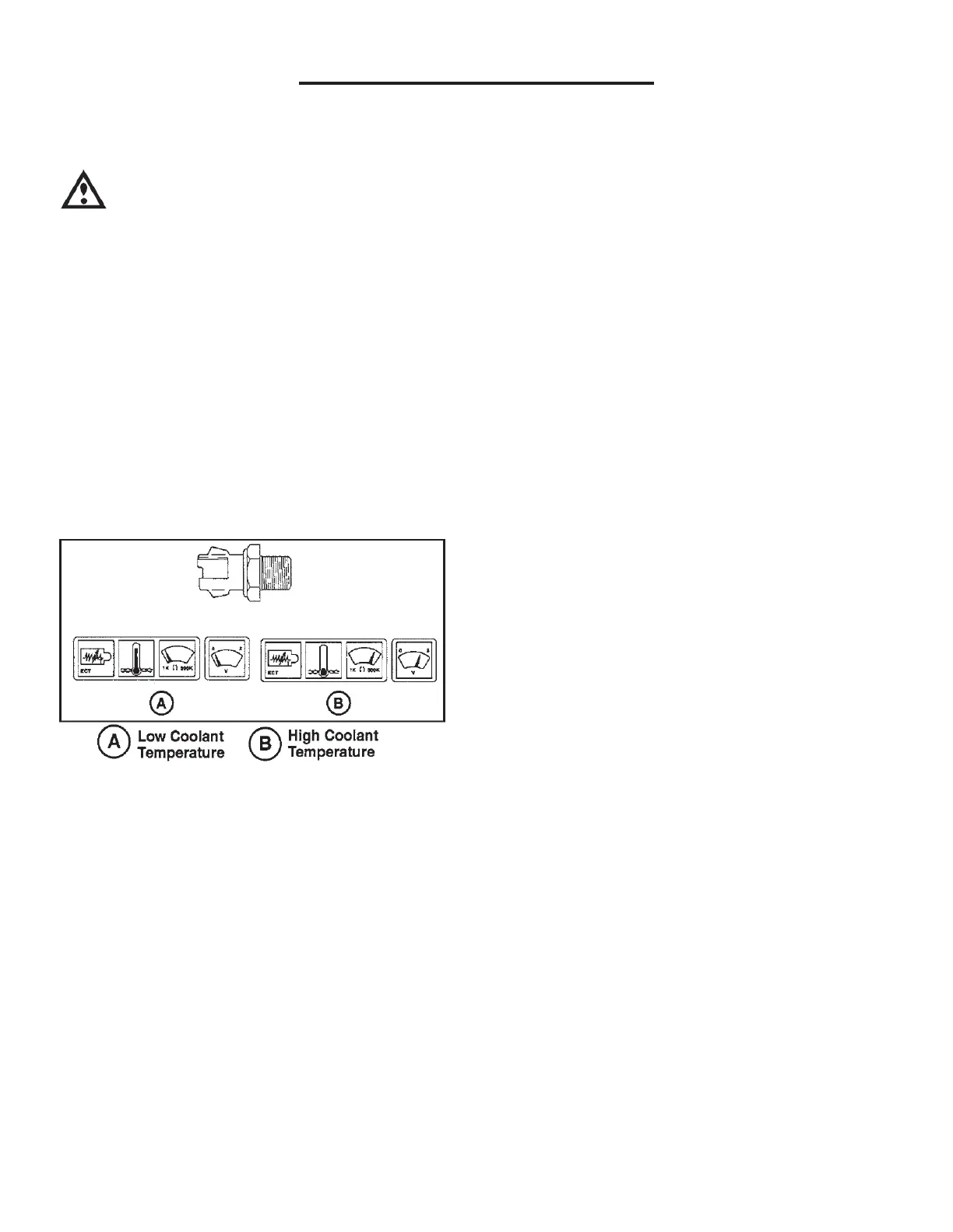
Engine Cylinder Head Temp.
(CHT) Sensor
Circuit Description
The engine cylinder head temperature (CHT) sensor is
a thermistor which measures the temperature of the
engine cylinder head. The GCP supplies a ground
(Gray/Red) from the sensor and monitors
voltage signal (Lt Green / Red) to the
sensor. When the engine coolant is cold, the sensor
resistance is high and the GCP will monitor a high
signal voltage at the CHT signal circuit. If the engine
cylinder head is warm, the sensor resistance is lower,
causing the GCP to monitor a lower voltage.
Engine cylinder head temperature (CHT) sensor
is a type of thermistor that converts engine
temperature to an electrical voltage signal.
The electrical resistance of the (CHT) sensor
changes with temperature. As engine coolant
temperature increases, the (CHT) resistance
decreases.
Output is a variable voltage signal which
typically ranges from 0.3 volt to 4.5 volts.
At -40°F (CHT) resistance is approximately
925K ohms.
At 77°F (CHT) resistance is approximately 30K
ohms.
At 248°F (CHT) resistance is approximately 1.2K
ohms.
NOTE: Complete list of temperature sensor
characteristics can be found on page 05-21 of
this section.
Diagnostic Aids
The (CHT) sensor shares the same ground with other
sensors. Check the ground circuit 359 (Gray)
if other shared components.
NOTE: Refer to Section 08 for further diagnostics.
Inspect the harness connectors for backed-out terminals,
improper mating, broken locks, improperly formed or
damaged terminals, and poor terminal-to-wire
connections. Inspect the wiring harness for damage. If
the harness appears to be OK, back probe the CHT
sensor connector with a digital voltmeter and observe
the voltage while moving connectors and wiring
harnesses related to the CHT sensor. A change in the
voltmeter display will indicate the location of the fault.