20
WSG-1068 GENERAL INFORMATION
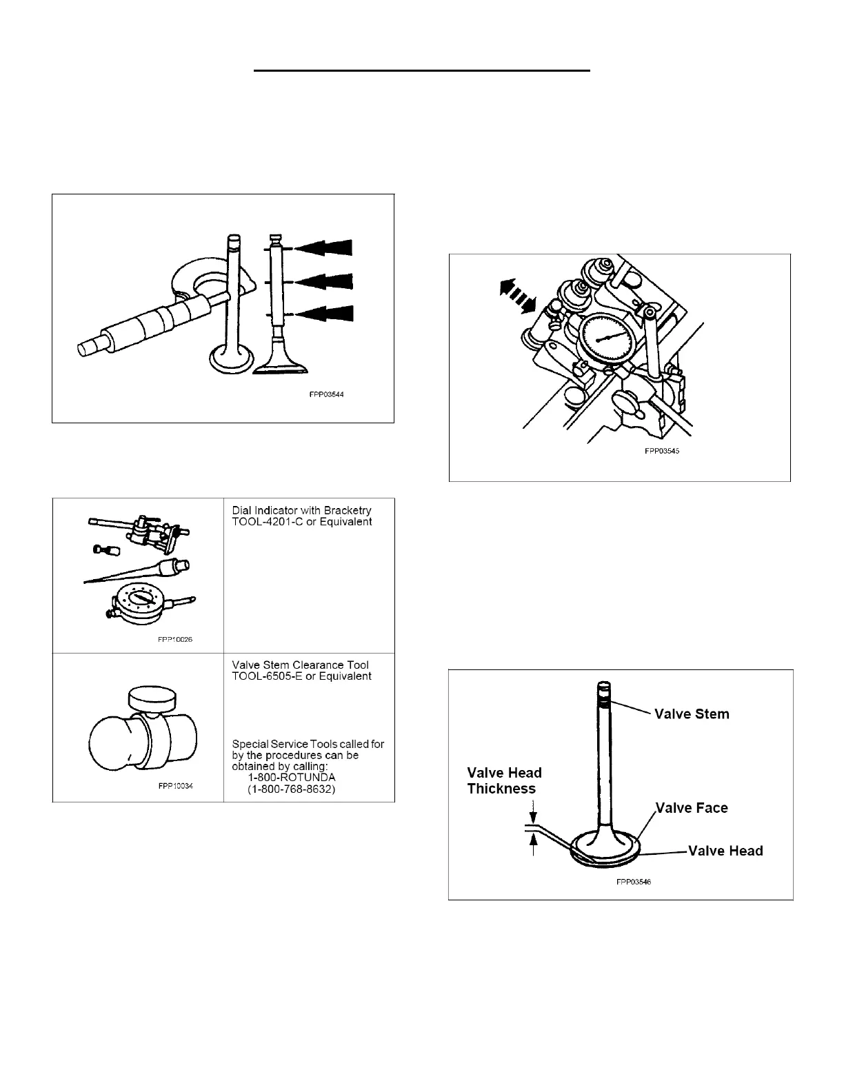
Valve Stem Diameter
Measure the diameter of each intake and
exhaust valve stem at the points shown. Verify
the diameter is within specification.
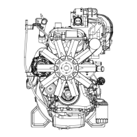
Valve Stem-to-Valve Guide Clearance
Special Tool(s)
NOTE: Valve stem diameter must be within
specifications before checking valve stem to valve
guide clearance.
NOTE: If necessary, use a magnetic base.
1. Install the Valve Stem Clearance Tool on the
valve stem and install the Dial Indicator with
Bracketry. Lower the valve until the Valve Stem
Clearance Tool contacts the upper surface of
the valve guide.
2. Move the Valve Stem Clearance Tool toward the
Dial Indicator and zero the Dial Indicator. Move
the Valve Stem Clearance Tool away from the
Dial Indicator and note the reading. The reading
will be double the valve stem-to-valve guide
clearance. Valves with oversize stems will need
to be installed if out of specification.
Valve Inspection
Inspect the following valve areas:
The end of the stem for grooves or scoring.
The valve face and the edge for pits, grooves or
scores.
The valve head for signs of burning, erosion,
warpage and cracking. Minor pits, grooves and
other abrasions may be removed.
The valve head thickness for wear.