7
WSG-1068 GENERAL INFORMATION
Camshaft Lobe Lift
Check the lift of each lobe in consecutive order and
make a note of the readings.
1. Remove the valve covers.
2. Remove the rocker arm seat bolts, rocker arm
seat and rocker arms.
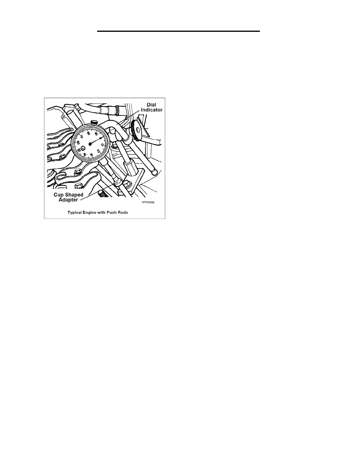
3. Make sure the lash adjuster is seated against
camshaft. Install the dial Indicator with Bracketry
so the ball socket adapter of the indicator is on
top of the hydraulic lash adjuster or the Cup
Shaped Adapter is on top of the push rod and in
the same plane as the lash adjuster push rod
movement.
4. Remove the spark plugs.
5. Connect an auxiliary starter switch in the starting
circuit. Crank the engine with the ignition switch
in the OFF position. Bump the crankshaft over
until the hydraulic lash adjuster is on the base
circle of the camshaft lobe. At this point, the
hydraulic lash adjuster will be in its lowest
position. If checking during engine assembly,
turn the crankshaft using a socket or ratchet.
6. Zero the dial indicator. Continue to rotate the
crankshaft slowly until the camshaft lobe is in
the fully-raised position (highest indicator
reading).
NOTE: If the lift on any lobe is below specified service
limits, the camshaft and any component operating on
worn lobes must be replaced.
7. Compare the total lift recorded on the dial
indicator with specifications.
8. To check the accuracy of the original dial
indicator reading, continue to rotate the
crankshaft until the indicator reads zero.
9. Remove the dial indicator, adapter and auxiliary
starter switch.
CAUTION: After installing rocker arms, do not rotate
the crankshaft until lash adjusters have had
sufficient time to bleed down. To do otherwise may
cause serious valve damage. Manually bleeding
down lash adjusters will reduce waiting time.
10. Install the rocker arm seats, rocker arms and
rocker arm seat bolts.
11. Install the valve covers.
12. Install the spark plugs.