222
WSG-1068 CHARGING SYSTEM
GENERAL INFORMATION
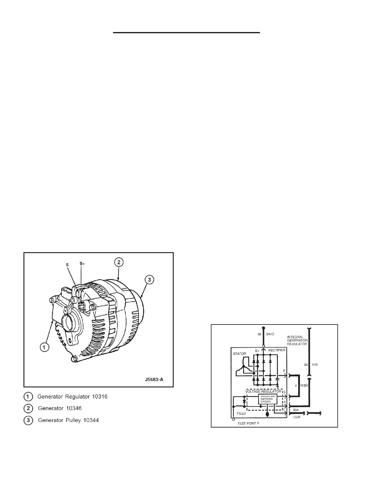
Generator
With the key in the RUN position, voltage is applied
through the charge indicator lamp “I” circuit to the
voltage regulator. This turns the voltage regulator on
allowing current to flow from the battery sense “A” circuit
to the generator field coil. When the engine (6007) is
started, the generator (10346) begins to generate
alternating (AC) current which is converted to direct (DC)
current by the rectifier internal to the generator. This
current is then supplied to the electrical system through
the Battery Positive voltage (B+) terminal located on the
rear of the generator.
Once the generator begins generating current, a voltage
signal is taken from the stator and fed back to the
voltage regulator “S” circuit, turning off the charge
indicator/lamp.
With the system functioning normally, the generator
output current is determined by the voltage at the “A”
circuit. This voltage is compared to a set voltage internal
to the voltage regulator, and the voltage regulator
controls the generator field current to maintain proper
generator output. The set voltage will vary with
temperature and is typically higher in the winter than in
the summer, allowing for better battery recharge.
Battery Positive Voltage (B+) Output
The generator output circuit 38 (BK/O) is supplied
through the battery positive voltage (B+) output
connection to the battery and electrical system. The B+
circuit is hot at all times. This circuit is protected by a 12
gage fuse link.
“I” Circuit
The “I” circuit, or ignition switch (11572), (R/Tan) is used
to turn on the voltage regulator. This circuit is closed with
the ignition switch in the RUN position. This circuit is
also used to turn the charge indicator lamp on if there is
a fault in the charging system operation or associated
wiring circuits.
“A” Circuit
NOTE: The “A” circuit is electrically hot at all
times.
The “A” circuit, or battery sense circuit, (Red) is used to
sense the battery voltage. This voltage is used by the
voltage regulator to determine the output. This circuit is
also used to supply power to the field coil. This circuit is
recommended to be protected by a 10 amp fuse or a
fuse link.
“S” Circuit
The “S” circuit, or stator circuit is used to feed back a
voltage signal from the generator to the voltage
regulator. This voltage, typically 1/2 battery voltage when
the generator is operating, is used by the voltage
regulator to turn off the charge indicator lamp.
Not used with this system.
Circuit Description