228
WSG-1068 CHARGING SYSTEM
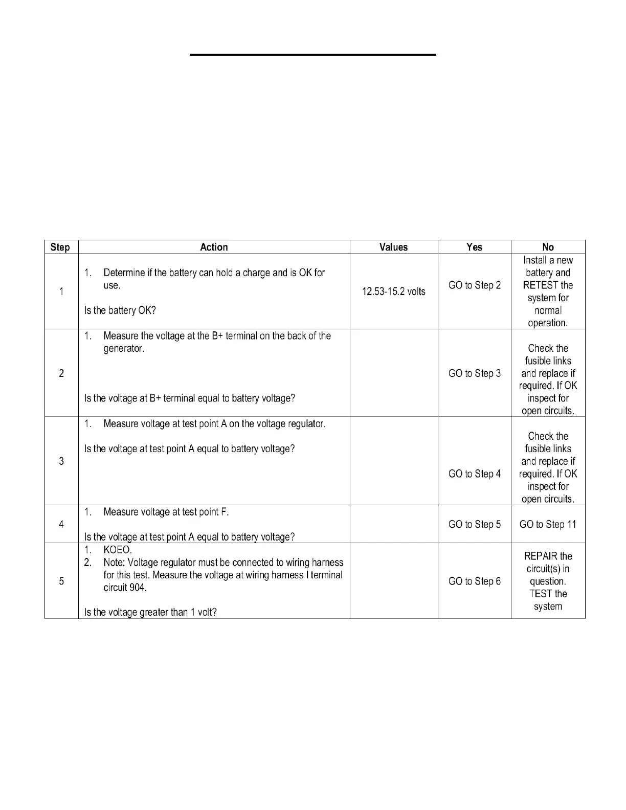
Pinpoint Test A: Generator Output Voltage
Inspection and Verification
1. Visually inspect for obvious signs of terminal corrosion and electrical harness damage.
2. Inspect fusible links and generator connector for bent or backed-out connector pins, or damage to wiring.
3. Visually inspect for and note auxiliary system connections not shown on the Recommended
Customer Connections Wiring Schematic.
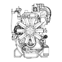
Normal Operation
With voltage applied to the generator I circuit, the regulator is activated, allowing current to flow from the sense A circuit to
generator field coil. The generator then generates an internal AC current, which is converted to a DC output by the
rectifier assembly internal to the generator, and is supplied to the battery through the B+ terminal. The S (stator) circuit is
used to feed back a voltage signal from the generator to the regulator. This voltage (typically half battery voltage) is used
by the regulator to turn off the charge indicator.