236
WSG-1068 STARTER SYSTEM
GENERAL INFORMATION
The function of the starting system is to crank the engine
at a speed fast enough to permit the engine to start.
Heavy cables, connectors, and switches are used in the
starting system because of the large current required by
the starter while it is cranking the engine. The amount of
resistance in the starting circuit must be kept to an
absolute minimum to provide maximum current for
starter operation. A discharged or damaged battery,
loose or corroded connections, or partially broken cables
will result in slower than normal cranking speeds, and
may even prevent the starter from cranking the engine.
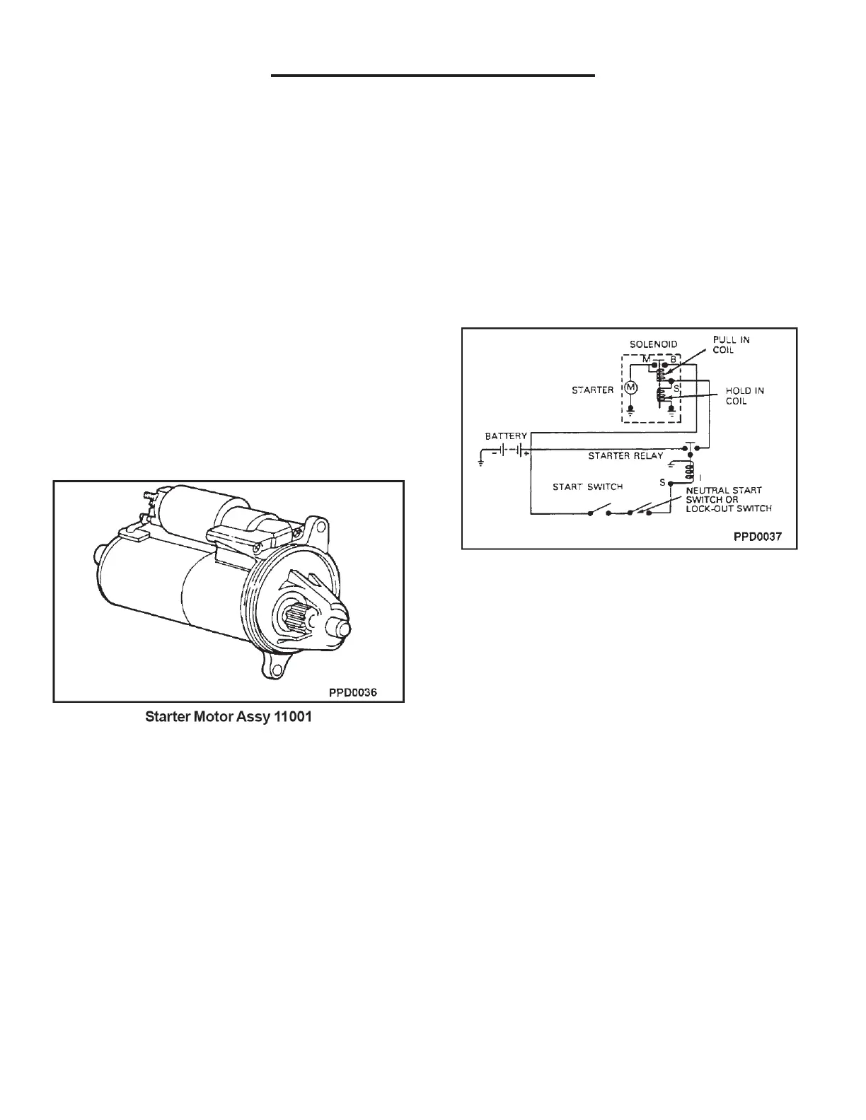
The starting system includes the permanent magnet
gearreduction starter motor with a solenoid-actuated
drive, the battery, a remote control starter switch (part of
the ignition switch), the starter relay, the heavy circuit
wiring, and may include starter lock-out, controlled by
the GCP through a starter lockout relay.
Field Service
Sequence Of Operation
1. The ignition switch is turned to the START
position.
2. A remote starter relay is energized, which
provides voltage to the starter solenoid. The
starter solenoid is energized, creating a
magnetic field in the solenoid coil.
3. The iron plunger core is drawn into the solenoid
coil.
4. A lever connected to the drive assembly
engages the drive pinion gear to the flywheel
ring rear.
5. When the iron plunger core is all the way into
the coil, its contact disc closes the circuit
between the battery and the motor terminals.
6. The current flows to the motor, and the drive
pinion gear drives the flywheel and the engine
crankshaft.
7. As current flows to the motor, the solenoid pull in
coil is bypassed.
8. The hold-in coil keeps the drive pinion gear
engaged with the flywheel.
9. The gear remains engaged until the ignition
switch is released from the START position.
NOTE: The GCP is programmed to lock the starter out
when the engine is operating over 600 rpm and the
following sequence takes place:
Starter Lockout Relay
See page 07-6 for further details.
1. During start up with key in the on position 12V
(B+) is applied to relay PIN 72 of the GCP (Lt
Gn/ Pr).
2. With ignition switch turned to the crank position,
current flows from ignition switch to relay circuit
87A (LB/Pink) 16G through relay and out circuit
30 (LB/Pink) 16G to starter solenoid.
3. The starter than should respond as in steps 2
through 9. The GCP keeps the starter relay
closed until it reads 400+ engine rpm. Over 600
rpm the GCP grounds circuit causing the relay to
open. This will prevent starter engagement while
engine is running.
NOTE: An overrunning clutch in the drive assembly
protects the starter from the excessive speeds during
the brief period before the driver releases the ignition
switch from the START position (as the engine starts).