CT TYPE QUANTITY LOCATION CONDUCTOR MEASURED DIRECTION OF ARROW
Consumption CT 2 Main panel
Conductor from the mains breaker to
the main panel or the utility meter
Towards the mains breaker
in the main panel
Production CT* 1 IQCombiner5/5C L1 of all PV branch circuits
Away from the PV (towards the PV
breakers in the IQCombiner5/5C)
IQBattery CT 1 IQCombiner5/5C L2 of IQ Battery branch
Away from the IQBattery (towards the
battery breaker in the IQCombiner 5/5C)
* IQCombiner5/5C has the production pre-wired in the box.
3. Ensure all EPC-controlled busbars and/or conductors are
protected with suitably rated overcurrent devices that
are appropriately sized for the busbar rating or conductor
ampacity.
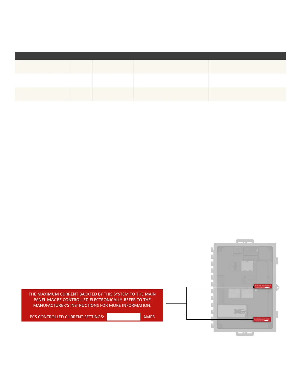
4. For sites with main panel upgrade (MPU) Avoidance mode
enabled, indicate, with a label, the maximum current setting for
backfeed that is controlled by EPC.
IQ Combiner 5/5C Quick Install Guide47
Section F - Operation
For grid-forming systems, apply the label on the
IQSystemController3/3G dead front (below the transparent
breaker position cover for mains breaker). Record the maximum
operating amps value on the label. The label is provided as part of
the IQSystemController Literature kit.
For grid-tied systems, apply the same label on the IQCombiner5
dead front (in one of the two recommended positions shown in the
image). Record the maximum operating amps value on the label. The
label is provided as part of the IQCombiner5/5C accessory kit.
 Loading...