EPSON FX-890/2190 Revision B
PRODUCT DESCRIPTIONS Interface 26
Note : In/Out refers to the direction of signal flow from the printer’s point of view.
1.2.3 USB Interface
Specifications
Standard: Based on
“Universal Serial Bus Specifications
Revision 1.1”
“Universal Serial Bus Device Class
Definition for Printing Devices Version 1.1”
Bit rate : 12 Mbps (Full Speed Device)
Data encording : NRZI
Adaptable connector : USB Series B
Recommended cable length : 2 meters
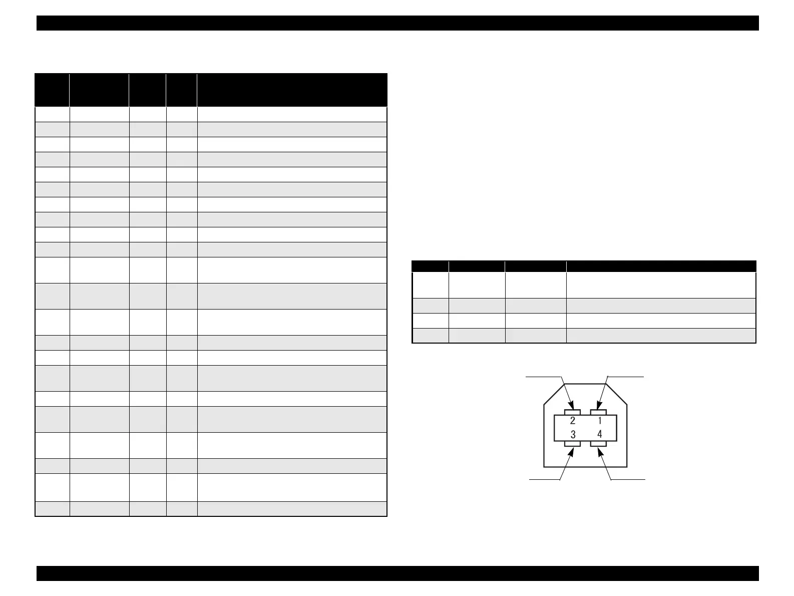
Connector pin assignment and signals :
Figure 1-8. USB Interface connector pin assignment
Table 1-27. Connector pin assignment (Reverse channel)
Pin No. Signal Name
Return
GND
Pin
IN/
Out*
Function description
1 HostClk 19 In Host clock signal.
2 DATA1 20 In Parallel input data to the printer. bit 0: LSB
3 DATA2 21 In bit 1
4 DATA3 22 In bit 2
5 DATA4 23 In bit 3
6 DATA5 24 In bit 4
7 DATA6 25 In bit 5
8 DATA7 26 In bit 6
9 DATA8 27 In bit 7: MSB
10 PtrClk 28 Out Printer clock signal.
11
PtrBusy /
DataBit-3,7
29 Out
Printer busy signal and reverse channel transfer
data bit 3 or 7.
12
AckDataReq /
DataBit-2,6
28 Out
Acknowledge data request signal and reverse
channel transfer data bit 2 or 6.
13
Xflag /
DataBit-1,5
28 Out
X-flag signal and reverse channel
transfer data bit 1 or 5.
14 HostBusy 30 In Host Busy signal.
31 -INIT 30 In Not used.
32
-DataAvail /
DataBit-0,4
29 Out
Data Available signal and reverse channel transfer
data bit 0 or 4.
36 1284-Active 30 In 1284 active signal.
18 Logic-H - Out
This line is pulled up to +5 V through 3.9 kΩ
resistor.
35 +5 V - Out
This line is pulled up to +5 V through 1.0 kΩ
resistor.
17 Chassis - - Chassis GND.
16, 33
19-30
GND - - Signal GND.
15, 34 NC - - Not connected.
Table 1-28. Connector pin assignment
Pin No. Signal name In/Out Function description
1VCC -
Cable power. Maximum power consumption is
100mA
2 -Data Bi-directional Data
3 +Data Bi-directional Data, pull up to +3.3V via 1.5K Ω resistor
4 Ground - Cable ground
Pin #2
Pin #4
Pin #3
Pin #1
 Loading...