EPSON FX-890/2190 Revision B
Disassembly and Assembly Printer Mechanism Disassembly 77
4.3 Printer Mechanism Disassembly
4.3.1 Printhead
1. Remove the top cover.(See Figure 4-2)
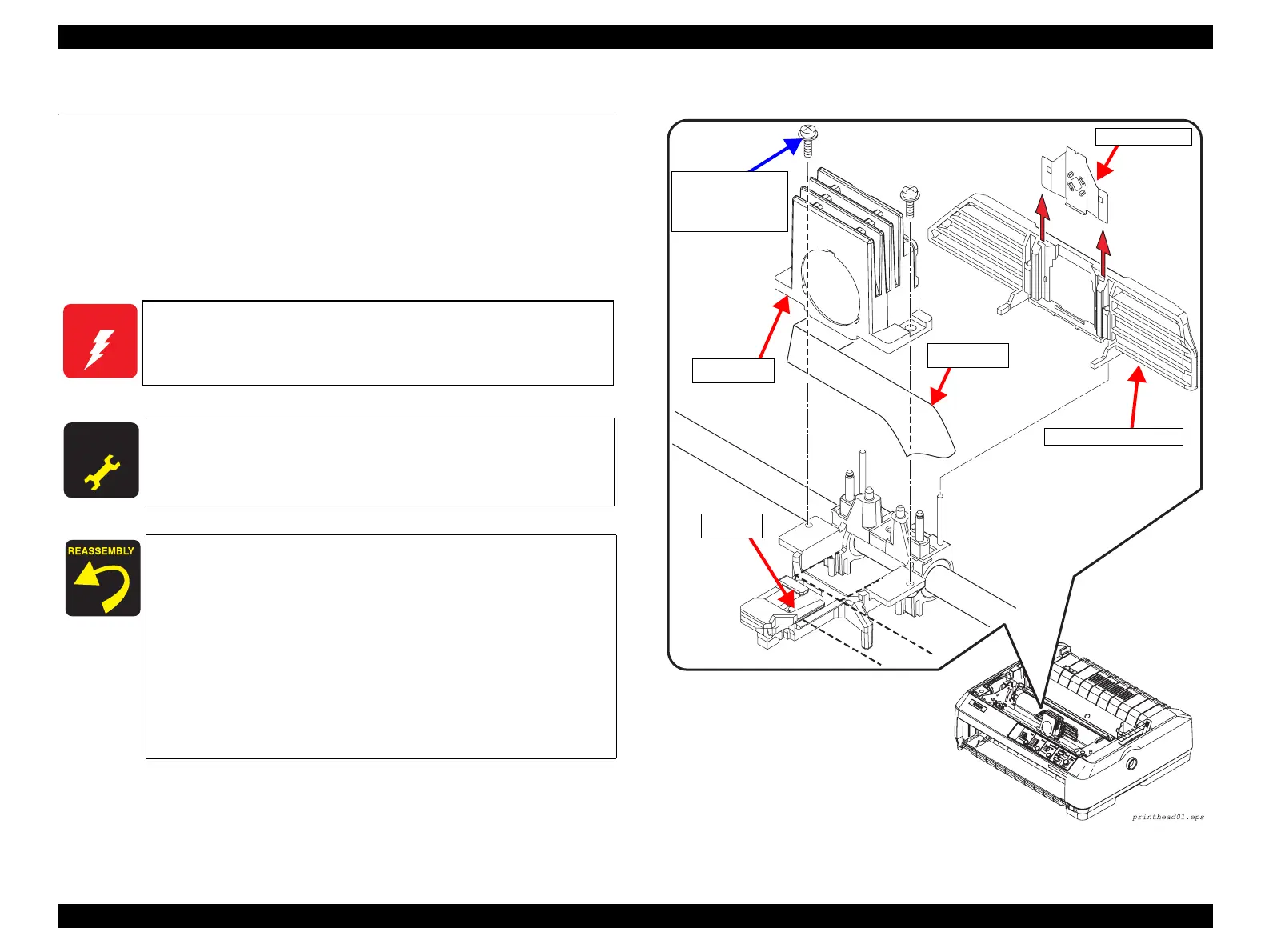
2. Remove the 2 CBS C (P2) (M3x8) screws securing the Printhead to the Carriage
Assembly.(See Figure 4-12)
3. Disconnect the head FFC from the Printhead and remove it.
Figure 4-12. Printhead Removal
W A R N I N G
Be careful with the Printhead when you handle it, as it may be very
hot right after printing.
A D J U S T M E N T
R E Q U I R E D
After installing the Printhead, make the following adjustments:
• Platen Gap Adjustment (p.95)
• Bi-d Adjustment (p.101)
When installing the Printhead with the Head FFC, put the
Head FFC under the hook of the carriage base.
Make sure that the Head FFC is propoerly connected to the
printhead. Do not connect the Head FFC at angle, to a
connector either on the printhead or the C524MAIN Board.
When replacing the Printhead, be sure to replace the Ribbon
Mask Holder (with the Ribbon Mask) at the same time. All
related parts are available as a kit as below.
HEAD KIT, ASP
Code: 1267348
Head FFC
Hook
CBS C(P2)
Screws (3x8) x2
Tightening Torque
: 0.7±0.1 N.m
Ribbon Mask
Printhead
Ribbon Mask Holder
 Loading...