EPSON FX-890/2190 Revision B
Disassembly and Assembly Overview 66
4.1 Overview
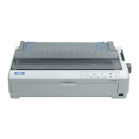
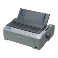
This section describes procedures for disassembling and assembling EPSON FX-890/
2190. Unless otherwise specified, disassembled units or components can be re-
assembled by reversing the disassembly procedure. Therefore, no assembly procedures
are included in this section. Precautions for any disassembly or assembly procedure are
described under the heading “CHECK POINT”. Any adjustments required after
disassembling the units are described under the heading “ADJUSTMENTS”.
4.1.1 Disassembly Precautions
Follow the precautions below when disassembling the printer.
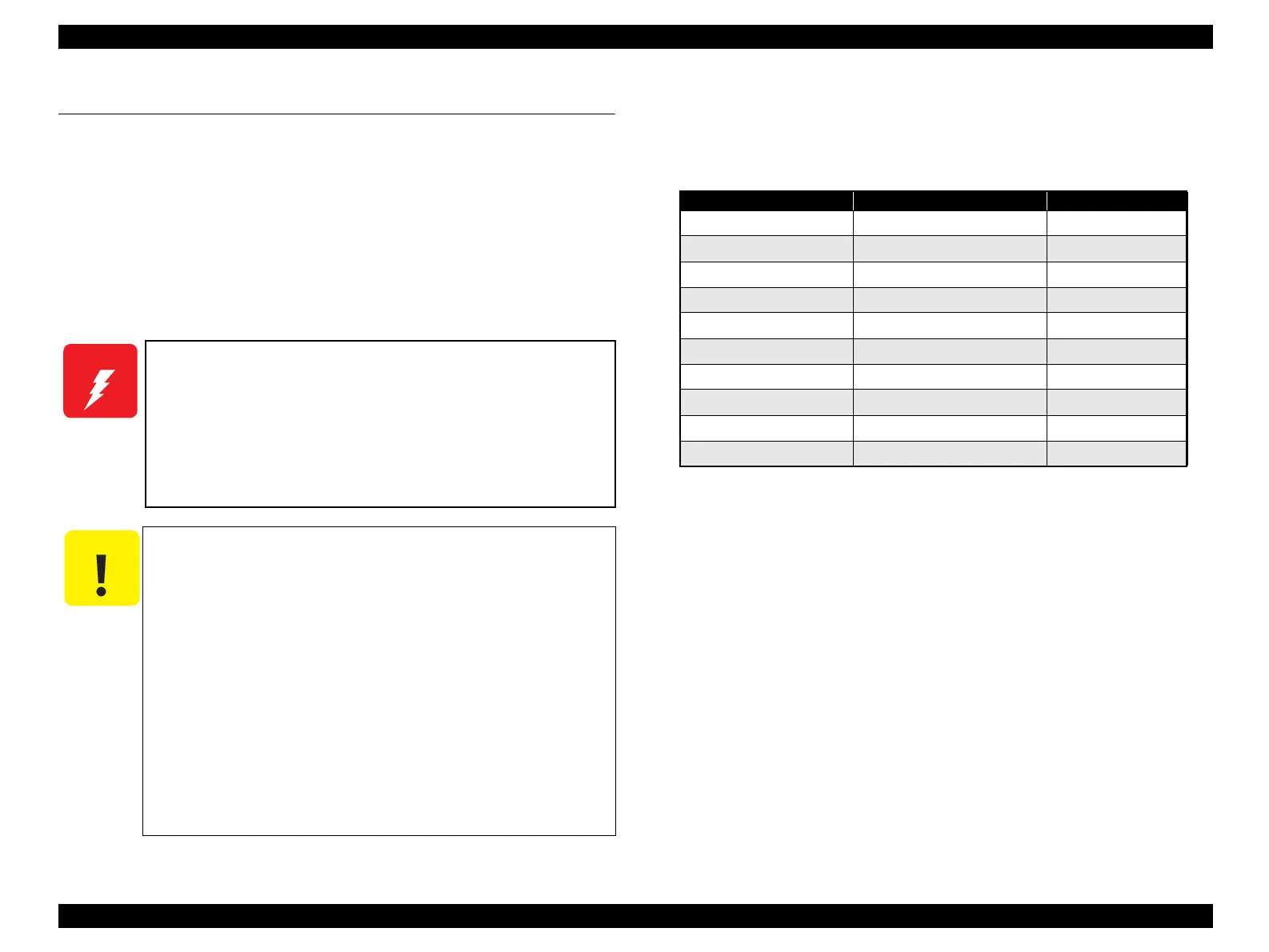
4.1.2 Tools and Instruments
The table below lists the tools and the instruments required for disassembling,
assembling or adjusting the printer. Use only tools that meet these specifications.
NOTE:All tools and instruments listed above are commercially available.
W A R N I N G
Before disassembling, assembling or adjusting the printer,
disconnect the power supply cable from the AC power socket.
Failure to do so might cause personal injury.
Be careful with the Printhead when you handle it as it may be
very hot right after printing.
Do not touch the heat sink attached to the switching FET (Q1)
on the power supply board right after power off, as it may be
very hot.
C A U T I O N
To maintain efficient printer operation, take the precautions
below:
Use only the recommended tools for maintenance work.
Use only the recommended lubrications and adhesives (See
Chapter 6.)
Adjust the printer only in the manner described in this
manual.
Always wear gloves for disassembly and reassembly to avoid
iujury from sharp metal edges.
To protect sensitive microprocessors and circuitry, use static
discharge equipment, such as anti-static wrist straps, when
accessing internal components.
Be aware that the existing drawings for FX-890 are substituted
for FX-2190. It is because no exclusive drawings for FX-2190
has been made since the major mechanical difference between
FX-890 and FX-2190 is width only.
Table 4-1. Tool and Instrument List
Name Specification EPSON Part No.
Phillips Screwdriver No.2 B743800200
Phillips Screwdriver No.1 B743800100
Box Driver 7.0mm Diagonal B741700200
Tweezers - B741000100
Round-nose pliers - B740400100
Thickness gage - B776702201
Soldering iron - B740200100
E-Ring holder Size:#6 B740800800
Multi-Meter OHM/Voltage/Current -
Oscilloscope Min. 50MHz -
 Loading...