EPSON FX-890/2190 Revision B
Troubleshooting Troubleshooting for Individual Units 64
3.3 Troubleshooting for Individual Units
3.3.1 Main Component Checking Point
The following components can be checked with a simple measurement tool, such as a
multi-meter, easily.
Motors
Note “*”: Set the meter to ohms. Then disconnect the Motor from the Main Board and check it
with printer power off.
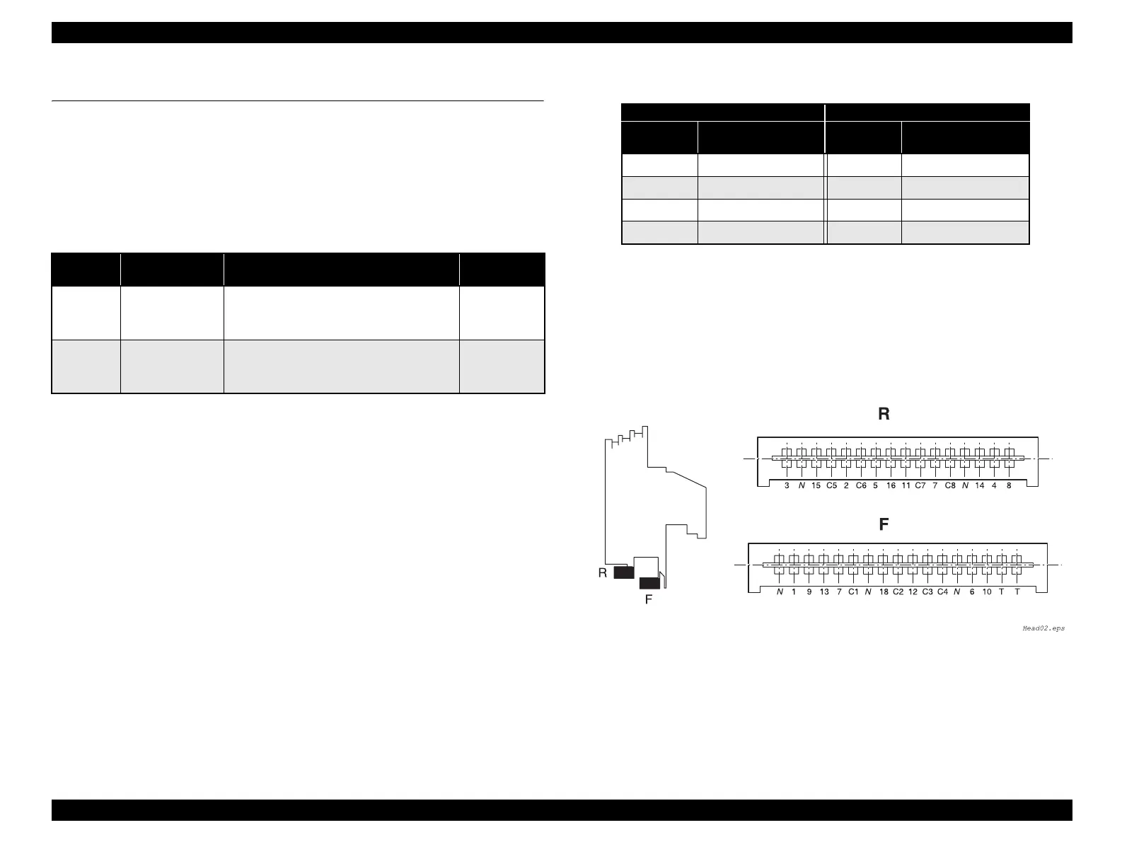
Printhead
Test Method : For example, place one lead on pin C1 and the other lead on
Test pin 1 to check #1 pin of the Printhead solenoid. Test
pin numbers match the printhead solenoid (dot wire)
numbers.
NOTE: Set the meter to ohms. Then disconnect the Motor from the Main Board
and check it with printer power off.
Specifications : 8.19 ± 0.8 Ω (at 25°C)
Note : 1~18: Wire numbers (Refer to “Figure 2-3“ in Chapter 2 for wire numbers.)
C1~ C8: Common terminals
T: Thermistor terminal
N: Not used
(The contact of the connector and FFC is positioned at the bottom side of the
connector.)
Figure 3-2. Printhead Connector Pin Assignment
Table 3-15. Motor Coil Resistance Test Points
Motor Test Pin Number Test Method*
Meter
Reading
PF Motor
(CN13)
1 and 3,
2 and 4
Place one lead on pin 1 (pin2) and the other
lead on pin3 (pin 4) on each of the test pins
to check the two motor phases.
16.0 Ω ± 10%
(at 25 °C per
one phase)
CR Motor
(CN12)
Common pin: 5
Test pins: 1, 2, 3
and 4
Place one lead on pin 5 and the other lead on
each of the 4 test pins to check the two motor
phase.
2.7 Ω±10%
(at 25°C per
one phase)
Table 3-16.
F R
Common
Line
Corresponding Wires
Common
Line
Corresponding Wires
C1 1, 7, 13 C5 2, 5, 11
C2 9 C6 3, 15
C3 10, 18 C7 16, 17
C4 6, 12 C8 4, 8, 14
 Loading...