EPSON FX-890/2190 Revision B
Disassembly and Assembly Main Components Disassembly 76
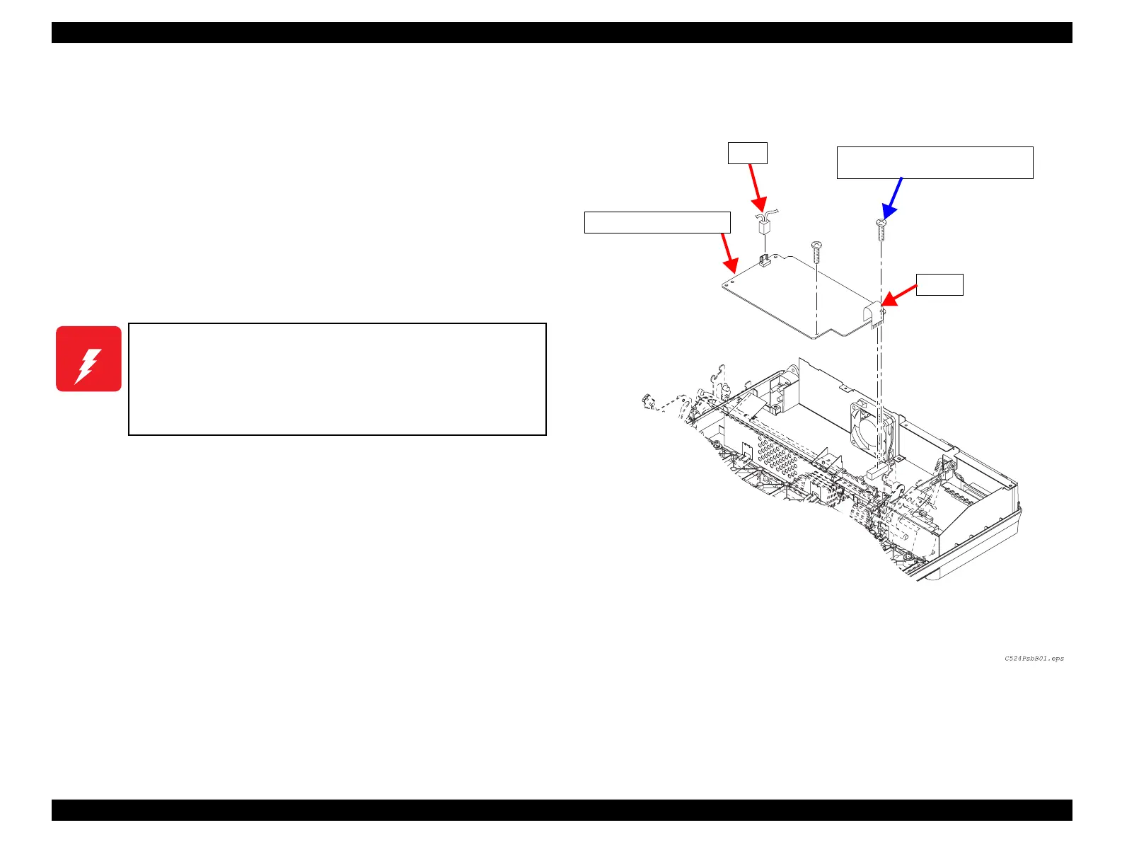
4.2.4 C524PSB/PSE/PSH Board
1. Perform Pre-Disassembly. (p.70)
2. Remove the Upper Housing. (p.72)
3. Remove the shield cover. (See Figure 4-8)
4. Disconnect the harness from the connector CN14 on the C524MAIN board.
(See Figure 4-11)
5. Disconnect the power cable from the connector CN1 on the C524PSB/PSE/PSH
Board.
6. Remove the 2 CBP (M3x12) screws securing the C524PSB/PSE/PSH Board to the
Lower Case, and remove the C524PSB/PSE/PSH Board.
Figure 4-11. C524PSB/PSE/PSH Board Removal
W A R N I N G
Before disassembling, assembling or adjusting the printer,
disconnect the power supply cable from the AC power socket.
Failure to do so might cause personal injury.
Do not touch the heat sink attached to the switching FET (Q1)
on the power supply board right after power off as it may be
very hot.
CN14
CBP Screws (3x12) x2
Tightening Torque: 0.88±0.1 N.m
C524PSB/PSE/PSH Board
CN1
 Loading...