EPSON FX-890/2190 Revision B
Disassembly and Assembly Main Components Disassembly 75
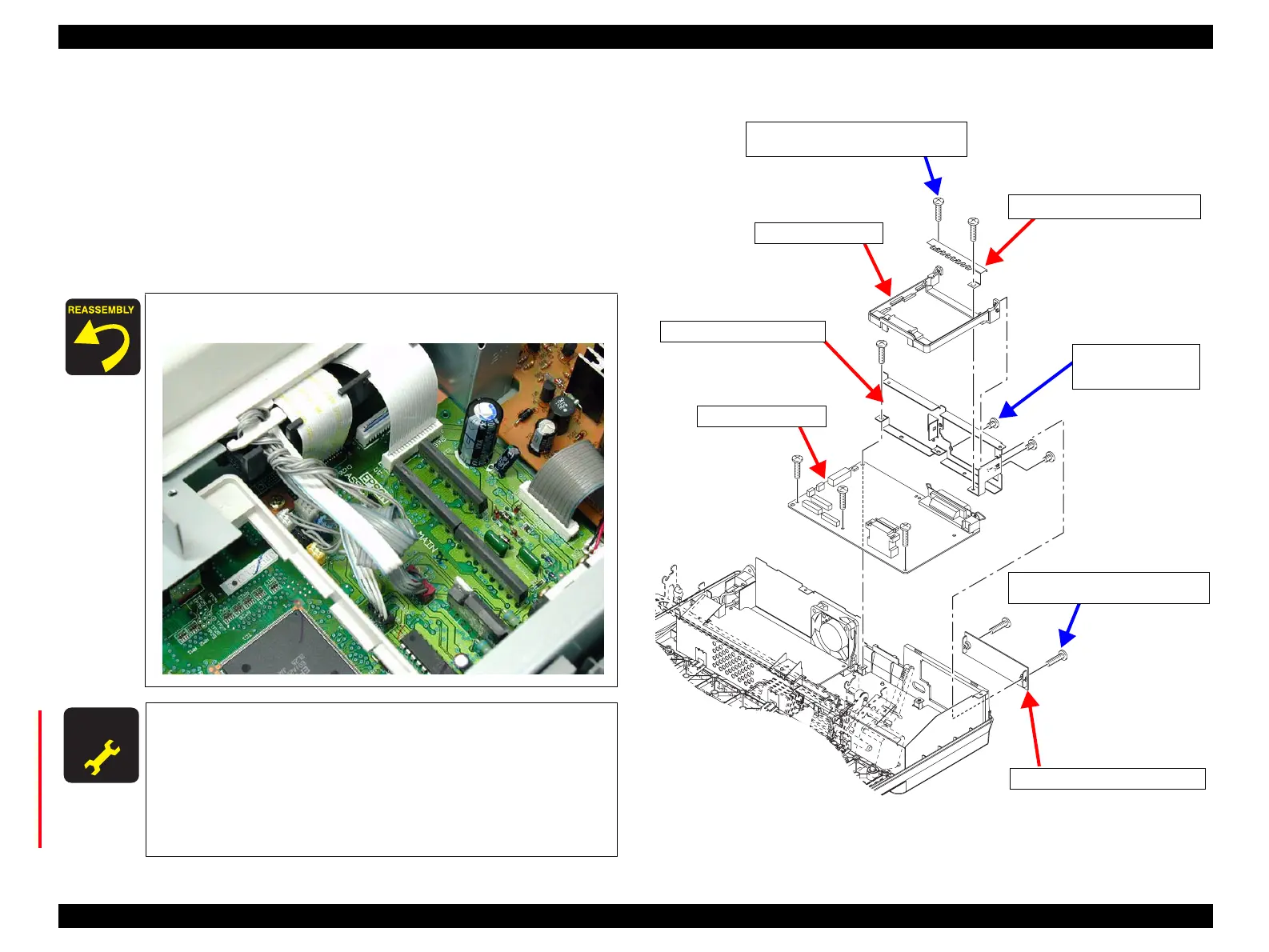
5. Remove the 2 CBS (M3x12) screws securing the COVER,CONNECTOR,UPPER
or the optional Type-B I/F Board to the I/F GROUNDING PLATE. (See Figure
4-10)
6. Remove the 6 CBP (M3x12) screws securing the C524MAIN Board to the lower
case.
7. Lift the rear side of the I/F GROUNDING PLATE slightly and remove the I/F
GROUNDING PLATE together with the C524MAIN board.
8. Remove the 3 CP (M3x4) screws securing the I/F GROUNDING PLATE to the
C524MAIN board. Then remove the I/F GROUNDING PLATE.
Figure 4-10. C524MAIN Board Removal 3
Lead the lead wires as shown below:
A D J U S T M E N T
R E Q U I R E D
Once the C524MAIN Board has been replaced, be sure to make
the following adjustments with the adjustment program. Refer to
“Adjustment Program” on page -97. :
• Bi-D Adjustment
• EEPROM Writing
• USB-ID Input
• Firmware Reloading
C524MainB_R01.eps
COVER, CONNECTOR,UPPER
GROUND PLATE, I/F, UPPER
CBP Screws (3x12) x6
Tightening Torque: 0.9±0.1 N.m
C524MAIN Board
GUIDE,I/F,BOARD
I/F GROUNDING PLATE
CP Screws (3x4) x3
Tightening Torque
: 0.48±0.1 N.m
CBP Screws (3x12) x2
Tightening Torque: 0.9±0.1 N.m
 Loading...