EPSON LX-300+II/300+II RTP/1170II Revision D
Disassembly and Assembly Disassembly and Assembly 82
4.2.7.10 PF Motor Assembly Removal
1. Remove the printer mechanism. (See 4.2.3 “Printer Mechanism Removal”.)
2. Remove the platen grounding wire from the platen.
3. Remove 1 screw (C.B.P., Tite, 3x10 F/ZN; Torque 0.59-0.78 N.M.) securing the PF
motor assembly to the right frame.
4. Release 1 hook at the right frame securing the PF motor assembly to the right frame
and remove the PF motor assembly.
Figure4-23. PF Motor Assembly Removal
4.2.7.11 Paper Feed Mechanism Disassembly
1. Remove the printer mechanism. (See 4.2.3 “Printer Mechanism Removal”.)
2. Remove the PF motor assembly. (See 4.2.7.10 “PF Motor Assembly Removal”.)
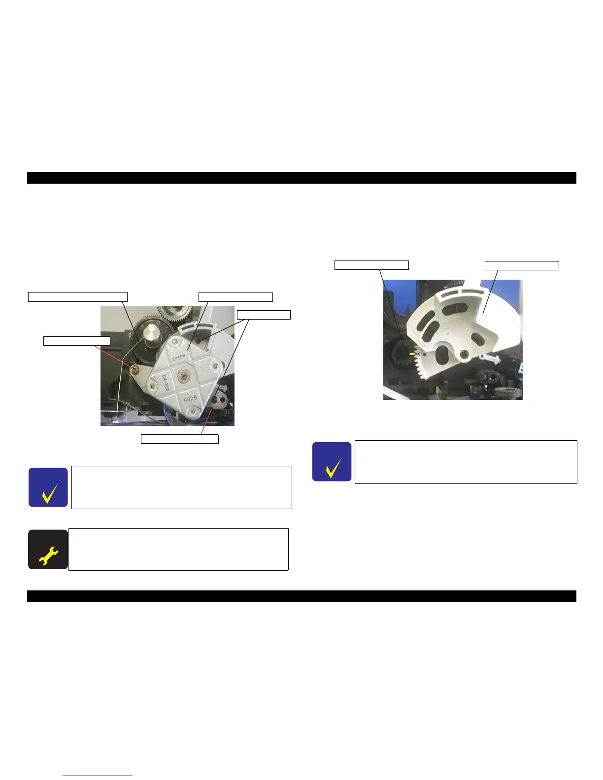
3. Remove the release lever.
Figure4-24. Release Lever Removal
4. Release the hook of the right frame securing the gear, 27.5 and remove the gear, plain
washer 5.2x0.3x10 and the compression spring, 1.18.
When installing the PF motor assembly to the right frame, be careful
to align the positioning pins with the respective positioning holes in
the motor bracket.
When the PF motor assembly is removed or replaced, perform the
platen gap adjustment, Bi-D adjustment, top margin adjustment,
and bottom margin adjustment.
When installing the release lever, be sure to align the marking on the
release lever with the marking on the release shaft.

 Loading...


